Questions? Email us at fireplaces@montigo.com or visit our website at www.montigo.com. Installation Operation & Maintenance ME38-DV-2 Homefire Modular Gas Fireplace Warning: Improper installation, adjustment, alteration, service or maintenance can cause injury or property damage. Refer to this manual. For assistance or additional information consult a qualified installer, service agency or the gas supplier.
ME38-DV-2 Homefire Table Of Contents Introduction About the M38 Series Modular Fireplaces: Introduction ............................................................................. 2 Installation Installing the Fireplace Shell ........................................... 3 Installing the Gasline ...................................................... 4 The Remote Switch ....................................................... 4 Direct Vent Installation ...................................................
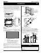
ME38-DV-2 Homefire Installation Installing The Fireplace Shell The fireplace may be installed in any location that that maintains proper clearances to air conditioning ducts, electrical wiring and plumbing. Safety, as well as efficiency of operation, must be considered when selecting the fireplace location. Try to select a location that does not interfere with room traffic, has adequate ventilation, and offers an accessible pathway for Direct Vent installation.
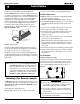
ME38-DV-2 Homefire Installation Installing The Gas Line The gas line must be installed before finishing the ME38-DV-2 Fireplace. Natural Gas requires a minimum inlet gas supply pressure of 5.5" W.C. & a manifold pressure of 3.5" W.C. Propane Gas requires a minimum inlet gas supply pressure of 11" W.C. & a manifold pressure of 10" W.C. Provision must also be made for a 1/8" N.P.T. plugged tapping and be accessible for test gauge connection immediately upstream of the gas supply controls to the appliance.
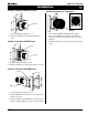
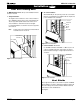
ME38-DV-2 Homefire Installation Installing Terminations with Built-In Frames Installing Heat Guards over Terminations 11 MTO-3F 11 MTKOG 1. Frame the termination opening to 11" x 11". 2. Fasten the termination to the studs using a minimum of 4 screws. Installing Terminations with MSR Frames 12 1. Ensure that the two long mounting brackets are facing the bottom of the termination. (See inset). This will provide more heat protection at the top of the termination, where temperatures are highest.
ME38-DV-2 Homefire Installation Top Vent Top Vent Venting Runs For the ME38-DV-2 Top Vent, there are two types of installations: A) Through-The-Wall Installations and B) Vertical (Through-The-Roof) Installations. A) Through-The-Wall Installations Before you install any venting, you must determine whether the venting run will be acceptable. Unacceptable venting can affect the fireplace's combustion.
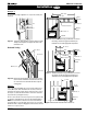
ME38-DV-2 Homefire Installation Top Vent Example 1: 150" max. 30" max. For our shortest venting configuration use components A and F (see Figure 9a). Heat Shield Termination Termination Heat Shield Solid Sections Exterior Wall MEL-90F/F Elbow Flex Section Hearth Figure 9a. Typical Top Vent installation. If the 90° elbow is installed directly on the fireplace, the height to the center of the termination is 44". Figure 10. Extended Installation using a combination of solid and flex venting.
ME38-DV-2 Homefire Installation B. Vertical (Through-The-Roof) Installations n Vertical Terminations must be installed: • minimum 2' (two feet) above the highest point where vent passes through the roof. • minimum 6' (six feet) from a mechanical air inlet • minimum 18" (1 1/2 feet) from a parapet wall. n Maximum vent height is 35 feet above fireplace. Note: Flame characteristics will change if the maximum vent height is used.
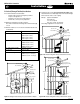
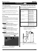
ME38-DV-2 Homefire Installation Rear Vent Rear Vent Venting Runs The ME38-DV-2 Rear Vent has three possible installations which do not require vertical lift: 1. Straight Installation. The height from the hearth to the center of the termination is 28 ¾". ME38-DV-2 Rear Vent versions are supplied with an 18" extension pipe (EXT-18) with female/female connections. For shorter installations, cut the EXT-18 to the desired length. 2. 45° Corner Installation.
ME38-DV-2 Homefire Installation B. Multi-Elbow Installations For more diffiicult installation situations, the ME38-DV-2 Rear Vent may be installed with two - 90° elbows and up to 15' of horizontal run. If using this installation option, you must adhere to the following guidelines: Rear Vent Installation Of Rear Vent DV ME38-DV-2 Rear Vent versions are supplied with an EXT-18 (female/ female) section.
ME38-DV-2 Homefire Installation Finishing Around the Fireplace Combustible mantels and mouldings may be safely installed over the top and on the front of the fireplace provided that they do not project beyond shaded area shown in Figure 19a. Side wall clearances are 3". Combustible surrounds may be installed with 3" clearance to the side of the fireplace as shown in Figure 19b.
ME38-DV-2 Homefire Installation Wiring for the optional Fan Kit All 38 Series Modular fireplaces may be equipped with optional fan or blower kits for circulating heat into the living space. Installations in Canada which employ the fans must be electrically grounded in accordance with CSA C22.1 Canadian Electrical Code Part 1 and/or Local Codes. Removing and Installing the Insert You may remove the insert to protect it from theft and damage during construction. 1.
ME38-DV-2 Homefire Installation Removing and Installing the Door Removing the Door: Remove the trim (as described on the next page) to access the door latches. Open the latches by pulling Part A upwards and towards you to disengage Part B from the door. Lift Part B clear of the door. Repeat for all three latches. Be sure to hold the door carefully so it does not fall. (See figure 23a.) Installing the Log Set Installing the Logs: The MD38-DV-2 is supplied with six ceramic fibre logs.
ME38-DV-2 Homefire Operation Installation Lighting Instructions See pages 15 and 16. Burner Adjustment Log 'C' Log 'B' The MD34-DV-2 fireplace is equipped with an adjustable burner, allowing you to raise or lower the flames. Operating the control knob as described below will adjust both the main burner and the ember burner. n To raise the flame height, turn the black knob (located behind the lower trim) counterclockwise. n To lower the flame height, turn clockwise.
ME38-DV-2 Homefire ME38-DV-2 Operation - Model ME38-DV-2 with Continuous Pilot For Your Safety - READ BEFORE LIGHTING: WARNING: If you do not follow these instructions exactly, a fire or explosion may result causing property damage, personal injury or loss of life. n If you cannot reach your gas supplier, call the Fire Department. A. This appliance has a pilot which must be lighted by hand. When lighting the pilot, follow these instructions exactly. B.
ME38-DV-2 Homefire ME38-DV-I-2 Operation - Model ME38-DV-I-2 with Honeywell Intermittent Pilot For Your Safety - READ BEFORE LIGHTING: WARNING: If you do not follow these instructions exactly, a fire or explosion may result causing property damage, personal injury or loss of life. A. This appliance is equipped with an ignition system that lights the pilot burner automatically. Do not attempt to light the pilot by hand. B. BEFORE LIGHTING smell all around the appliance area for gas.
ME38-DV-2 Homefire Maintenance CAUTIONS n Fireplace gas control must be in the “OFF” position and pilot and main burners extinguished when cleaning appliance with a vacuum. n Doors and logs can get very hot. Handle only when cool. Gas Control Valve Power Generator Pilot Adjustment Screw Wall Switch General n Have the fireplace installation inspected yearly, including a visual check of the vent system, the burner and the pilot flame.
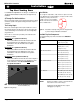
ME38-DV-2 Homefire Notes Maintenance Troubleshooting ME38-DV-I-2 HONEYWELL SV 9500 /SV9600 Troubleshooting Sequence NOTE: Before Troubleshooting, Familiarize Yourself With START The Startup And Checkout Procedure. INSET · Turn Gas Supply off · Set thermostat to call for heat SV9500/SV9600 is powered (24 VAC nominal) NO YES NO Igniter warms up and glows red. Pilot Valve opens. YES Turn gas on.
ME38-DV-2 Homefire Warranty The Warranty The Companies warrants the Montigo Gas Appliance to be free from defects in materials and workmanship at the time of manufacture. On the Montigo, there is a tenyear warranty on the firebox and its components, a five-year warranty on the main burner and pilot burner, and a one-year warranty on the gas control valve and fibre logs. Glass, plated/painted finishes, and refractory lining are exempt.
ME38-DV-2 Homefire Appendix A - Accessories 1 2 3 Available Options and Accessories: 1. Add-on Bay Window 2. Hand-Held Remote Control 3. Cross Flow Blower Kit 4. 4-Fan Kit 5. 4-Piece Picture Frame Surround (PFS) 6. 3-Piece Picture Frame Surround (PFO) 7. Door Cover, Square (DF0) 8. Door Cover, Arched (DFA) 9. Horizontal Trim Kits (Black, Brass, Nickel) 10. Replacement Logset 4 6 9 Page 20 5 8 7 10 Part No.
ME38-DV-2 Homefire Appendix B - Termination Locations A = clearance to the termination frame above grade, veranda, porch, deck, or balcony [16 inches (41 cm) minimum] B = clearance to door, or sides and top of window, that may be opened [16 inches (41 cm) minimum for appliances ≤100 000 BTU/H (30kW)] C = clearance to bottom of window that may be opened horizontally [36 inches (92 cm) minimum for appliances ≤100 000 BTU/H (30kW)] M = clearance to mechanical air supply inlet [*6 feet (1.
XG0110 Rev. 8 - 07/02 Canadian Heating Products Inc. Montigo Del Ray Corp.