
Specifications

Only For Qualied Installers
The Conquest can burn either natural gas or pro-
pane, but requires a change-over kit for natural gas. The
label on the burner system module indicates the fuel for
which it is equipped. A second label, (on the valve) also
indicates the fuel type.
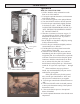
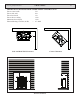
The gas inlet is located on the bottom right side of
the stove. The inlet tting is a 1/2” male are tting.
A separate gas shut-off valve and a 1/8” N.P.T.
plugged tapping should be installed immediately upstream
of the connection to the appliance.
The Conquest Direct Vent Gas Heater must be dis-
connected from the gas supply piping during any pressure
testing of that system at pressures in excess of 1/2 psig
(3.5 kPa).
The Conquest gas control valve must be in the OFF
position during any pressure testing of the gas supply sys-
tem at pressures equal to or less than 1/2 psig (3.5 kPa).
WARNING: To avoid pipe compounds from
entering into the gas train, apply compounds only
to male pipe threads and do not apply compound
CAUTION: TEST ALL JOINTS FOR LEAKS
BEFORE OPERATING.
Gas Pressure Requirements:
Correct gas pressure and the use of a properly sized
gas supply line are essential for the safe and efcient
performance of this appliance. Make sure that the plumber
or gas supplier checks the gas supply line and gas pres-
sure at installation.
NOTE: Improper gas pressure can affect heater
performance, ame color, or cause pilot outage.
WARNING: This product must be installed by a
licensed plumber or gas tter when installed within the
Commonwealth of Massachusetts.
Natural Gas:
Maximum inlet pressure 7.0” w.c. (1.74 kPa)
Minimum inlet pressure 5.0” w.c. (1.25 kPa)
Gas manifold pressure 3.8” w.c. (0.87 kPa)
Maximum inlet pressure 13” w.c. (3.24 kPa)
Minimum inlet pressure 11.5” w.c. (2.74 kPa)
Gas manifold pressure 11” w.c. (2.49 kPa)
Do not use this heater if any part has been under
water or exposed to moisture corrosion. Immediately
call a qualied service technician to inspect the heater
and replace any part of the control system and any
gas control which has been under water.
Ne pas se servir de cet appareil s’il a étre plongé dans
l’eau, complètement ou en partie. Appeler un technicien
qualié pour inspecter l’appareil et remplacer toute partie
du système de contrôle et toute commande qui ont été
plongés dans l’au.
If appliance is installed directly on carpeting,
tile, or other combustible material other than wood
ooring, the appliance shall be installed on a metal
or wood panel extending the full width and depth of
the appliance.
Keep areas around air openings into the combus-
tion chamber free of obstructions, and do not block
any panels where access is needed for servicing.
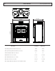
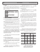
Pipe Length Schedule 40 Pipe Tubing, Type L
(Feet) Inside Diameter Outside Diameter
N.G. L.P. N.G. L.P.
0-10 1/2” 3/8” 1/2” 3/8”
1.3 cm 1.0 cm 1.3 cm 1.0 cm
10-40 1/2” 1/2” 5/8” 1/2”
1.3 cm 1.3 cm 1.6 cm 1.3 cm
40-100 1/2” 1/2” 3/4” 1/2”
1.3 cm 1.3 cm 1.6 cm 1.3 cm
100-150 3/4” 1/2” 7/8” 3/4”
2.0 cm 1.3 cm 2.3 cm 2.0 cm
RECOMMENDED GAS PIPE DIAMETER
-
NATURAL GAS
PROPANE