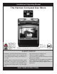
Installation & Operating Manual The Harman Conquest Gas Stove Tested to ANSI Z21.88-2002, CSA2.33-M02 and CAN-CGA-2.17-M91 “Ce manuel est disponible en Français sur demande” R12 SAFETY NOTICE WARNING: If the information in these instructions are not followed exactly, a fire or explosion may result causing property damage, personal injury or loss of life. Installation and service must be performed by a qualified installer, service agency, or the gas supplier.
SAFETY NOTICE Please read this entire manual before you install and use your new room heater. Failure to follow instructions may result in property damage, bodily injury, or even death. FOR USE IN THE U.S. AND CANADA. SUITABLE FOR INSTALLATION IN MOBILE HOMES IF THIS HARMAN STOVE IS NOT PROPERLY INSTALLED, A HOUSE FIRE MAY RESULT. FOR YOUR SAFETY, FOLLOW INSTALLATION DIRECTIONS. CONTACT LOCAL BUILDING OR FIRE OFFICIALS ABOUT RESTRICTIONS AND INSTALLATION INSPECTION REQUIREMENTS IN YOUR AREA.
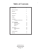
Table of Contents Introduction 4 Safety Precautions 4 Operation 5 Specifications 8 Clearances 9 Venting 10 Installation Changing To Natural Gas 22 22 Option Installation Thermostat Remote Control Glass Grill Blower 26 26 26 27 Maintainence Wiring Diagram Parts 28 30 31 Trouble Shooting 33 Warranty 37 Manufactured by The Harman Stove Company 352 Mountain House Rd.
Introduction The Harman Conquest Direct Vent Gas Stove is a listed gas-fired direct vent room fireplace tested by Intertek Testing Services/Warnock Hersey to ANSI Z21.88-2002-CSA 2.33-2002 and CANL/CGA2.17-M91. The installation of the Conquest Direct Vent Gas Stove must conform with local codes, or in the absence of local codes, with National Fuel Gas Code, ANSI Z223.1 — latest edition and CAN 1 B1-149.1 and .2 Installation Code. Also for use in mobile (manufactured) homes after home is sited.
OPERATION WARNING: If you do not follow these instructions exactly, a fire or explosion may result causing property damage, personal injury, or loss of life. A. This appliance has a pilot. When lighting the pilot, follow instructions exactly. B. Before operating, smell all around the appliance area for gas. Be sure to smell next to the floor because some gas is heavier than air and will settle on the floor. What to do if you smell gas: • Do not try to light any gas appliance.
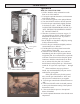
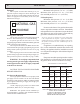
OPERATION Operation Piezo Ignitor Button High-Low Gas Control PILOT HOW TO LIGHT THE FIRE 1. STOP! Read the safety information on the front cover of this manual. 2. If using the optional thermostat, set thermostat to the lowest setting. 3. Turn off electric power to the optional blower. 4. Turn the ON-OFF switch to the OFF position. 5. Push in the gas control knob slightly and turn it clockwise to “OFF.” NOTE: THE KNOB CANNOT BE TURNED FROM “PILOT” TO “OFF” UNLESS IT IS PUSHED IN SLIGHTLY.
OPERATION 15. Set the High-Low Regulator to desired setting: Turn fully counterclockwise for High and fully clockwise for Low. If using a Thermostat, keep on High setting. Flame Height Adjuster NOTE: An odor, resulting from the initial heating of new materials in your heater, is not unusual during the first fire, and in most cases will disappear after an hour or two. HOW TO TURN OFF THE FIRE 1. If using optional thermostat, set thermostat to the lowest position. 2.
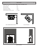
VENTING Only For Qualified Installers 14.102 32.094 29.396 24.974 RATINGS Natural Propane Input Rating (Btu/hr)(0-4500 ft.)(0-1375 m) 29000 29000 Min. Input Rating (Btu/hr)(0-4500 ft.)(0-1375 m) 14900 14100 Orifices (DMS)(0-4500 ft.)(0-1375 m) Manifold Pressure (in w.c./kPa) 37 3.8/.95 11.0/2.75 1.1/.27 2.8/.7 5.0/1.25 11.5/2.87 21375 21854 Min. Manifold Pressure (in w.c./kPa) Min. Inlet Pressure (in w.c./kPa) 53 Max.
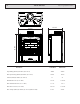
VENTING Only For Qualified Installers MINIMUM CLEARANCES FROM COMBUSTIBLE CONSTRUCTION Unit to corner walls 2 in. Unit to side wall 8 in. Unit to back wall 3 in. Unit to alcove ceiling 16 in. Maximum alcove depth 16 in. Electrical Rating: 120 Volts, 60 Hz, < 0.
VENTING 10 Only For Qualified Installers Burn Only the Fuel for which the Heater is Equipped Natural Gas: Maximum inlet pressure 7.0” w.c. (1.74 kPa) The Conquest can burn either natural gas or pro- Minimum inlet pressure 5.0” w.c. (1.25 kPa) pane, but requires a change-over kit for natural gas. The Gas manifold pressure 3.8” w.c. (0.87 kPa) label on the burner system module indicates the fuel for which it is equipped. A second label, (on the valve) also indicates the fuel type.
Only For Qualified Installers VENTING 11 Use Only Approved Venting This appliance has been tested and is listed for installation with Simpson Duravent GS venting components. The Simpson Duravent GS warranty will be voided, and serious fire, health, or other safety hazards may result from any of the following actions: • Installation of any damaged Duravent GS component. • Unauthorized modification of the Duravent GS System.
VENTING 12 Only For Qualified Installers Selkirk Direct-Temp Vs. Simpson Dura-Vent Direct Vent GS Selkirk Direct-Temp Stock No.
VENTING Only For Qualified Installers Secure Vent Direct Vent System - 4” x 6-5/8” and 5” x 8” Description Secure Vent Cat No. Simpson Dura-Vent Direct Vent GS Stock No. 13 Cross Reference List Secure Vent Cat No. Simpson Dura-Vent Direct Vent GS Stock No. Length 6” (Galvalume).........................SV4L6 Length 6” (Black)................................SV4LB6 Length 12” (Galvalume).......................SV4L12 Length 12” (Black)..............................SV4LB12 Length 24” (Galvalume).
VENTING Montigo Direct Vent Only For Qualified Installers Standard Series Direct Vent (4”/ 7”) Description Order Code Horizontal Terminations 3” length, no mounting frame (use with MSR or MOSR) .................... MTO3 3” Termination, with integral mounting frame .................................... MTO3F Vertical Termination Termination for vertical installations ..................................................
Only For Qualified Installers VENTING Montigo Direct Vent 15 Standard Series Direct Vent (4”/ 7”) Description Order Code Snorkel Terminations 18” vertical rise .............................................................................. SNK47-2 30” vertical rise ...............................................................................SNK47-3 Heat Guard Fits all Standard Series (4/7”) terminations ........................................
VENTING Montigo Direct Vent Only For Qualified Installers Premium Series Direct Vent (5”/8”) Description Order Code Horizontal Terminations 3” Termination with no mounting frame (male connector). ..................... PTO3 (use with MSR or MOSR). 3” Termination & mounting frame (male connector). ............................. PTO3F Vertical Termination Termination for vertical installations (male connector) ...........................
Only For Qualified Installers VENTING Montigo Direct Vent 17 Premium Series Direct Vent (5”/8”) Description Order Code Snorkel Terminations 18” vertical rise ......................................................................................SNK58-2 30” vertical rise ......................................................................................SNK58-3 Insulated Offset Box M38DV-ST offset box. Used only on the M38DV-ST when a shelf or T.V. stand is required above the fireplace. ...............
VENTING 18 Only For Qualified Installers EXCELDirect - Component List Liste des composants Longueurs Longueur 6’’, Galvalume Longueur 6’’, Noire Longueur 12’’, Galvalume Long���������������� ueur 12’’, Noire Longueur 24’’, Galvalume Longueur 24’’, Noire Longueur 48’’, Galvalume Longueur 48’’, Noire Longueur flexible 36’’ Longueur télescopique 12’’, Galvalume Longueur télescopique 12’’, Noire Coudes Coude 45º, Galvalume Coude 45º, Noir Coude 90º, Galvalume Coude 9�������� 0º, Noir Supports et coupe-feux
Only For Qualified Installers This appliance must not be connected to a chimney flue serving a separate solid fuel burning appliance. Venting terminals shall not be recessed into a wall or siding. VENTING 19 Venting with 6 5/8” x 4” Pipe Maximum of four 450 elbows allowed. Subtract three feet of total horizontal pipe length for each of the 3rd and 4th 450 elbows used. Maximum of two 900 elbows allowed. Subtract five feet of total horizontal pipe length for second elbow.
VENTING Only For Qualified Installers (a) Termination 10 ft. (3 m) or less from ridge, wall, or parapet (b) Termination more than 10 ft. (3 m) from ridge, wall, or parapet The following diagram and table detail the restrictions on the vent terminal location.
Only For Qualified Installers A= B= C= D= E= F= G= H= I= J= K= L= M= Clearance above grade, veranda, porch, deck, or balcony Clearance to window or door that may be opened Clearance to permanently closed window Vertical clearance to ventilated soffit located above the terminal within a horizontal distance of 2 feet (61 cm) from the center line of the terminal Clearance to unventilated soffit Clearance to outside corner Clearance to inside corner Clearance to each side of center line extended above m
VENTING Damper Settings Top Vent Only 22 Only For Qualified Installers Vent damper shown in the Maximum Draft”OPEN” position for top vent. Note: This would be the Minimum Draft”CLOSED” position if a rear vent was installed. A vent damper is provided to allow fine tuning of the draft. Too little draft will cause flames to be too long with black tips and too much draft will cause flames to be short and blue. To adjust the damper, burn the unit on High 10 minutes or more.
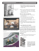
INSTALLATION Only For Qualified Installers 23 Changing to Natural Gas Natural Gas Conversion Kit NG Conversion Instructions 1 Remove four bolts and remove burner module from stove. NG Pilot Orifice NG Conversion label NG Orifice #37 NG Valve Conversion Module 2 Use a 1/2” deep well socket to remove the LP #53 orifice and replace with the #37 Natural gas orifice from the kit. Natural Gas Kit Part No. 1-00-09112 This kit is only for use in the Conquest direct vent gas stove.
INSTALLATION Only For Qualified Installers 5 Reinstall burner module back into the stove with the four bolts that were removed. Check gasket for damage and replace if necessary. Check for gas leaks when finished. Note: The higher the orifice number the smaller hole in the tip. For example, a number 52 orifice has a larger hole than a number 60 orifice. 6 Place conversion sticker (provided in Kit) on the valve. This is to permanently mark the valve that it has been converted to Natural Gas.
Only For Qualified Installers INSTALLATION 25 Log Placement Rear Log Wool Nuggets Front Log Place the rear log behind the front log with the branch resting on the front log on the right side as shown. Andirons Air Deflector Before lighting a fire check that the rear log is as far back against the rear wall as possible. The front log should be slid rearward in it’s position between the andirons and deflector plate.
INSTALLATION - Options Round Tile Not Used On Top Vent Only For Qualified Installers Tile Kit Each tile kit contains six tiles and fifteen allenset screws. If the Conquest is installed as a top vent, then the round tile is not used. If it is installed as a rear vent, then the trim ring is not used. Installing Tiles Below each tile opening are three threaded holes. In some cases it may be helpful to remove extra paint from the treads with a 1/4-20 tap. Trim Ring Not Used On Rear Vent.
Only For Qualified Installers INSTALLATION - Options Connecting the Optional Thermostat If the optional thermostat is used, it must be plugged into the TH terminals located on the valve. When installing a millivolt control system, use only a special low resistance thermostat. DO NOT USE A REGULAR HEATING THERMOSTAT. Be sure that all electrical connections are clean, free from corrosion, and tight. Inspect connections periodically to confirm that no corrosion has built up over time.
INSTALLATION - Options Optional Blower Only For Qualified Installers The Blower Kit (Part # 1-00-09102) includes a blower assembly ready to bolt to the left side of the stove and a blower chamber cover. The blower has a variable speed control knob to adjust the blower speed as desired. A special switch is used to automatically start the blower when the stove temperature is hot enough to blow warm air.
MAINTENANCE A qualified service person should conduct an annual inspection and maintenance of your Conquest, its venting, and the installation to keep it running safely and efficiently. The following procedures should be performed only by a qualified service person. The gas supply should be turned off whenever a maintenance procedure is performed. If the glass door or side doors are removed for servicing, they must be replaced prior to operating the stove.
MAINTENANCE 30 Inspecting the Venting An inspection of both the inner and outer pipes of the venting system should be made during the annual service appointment. There must be no blockage and be in good repair. The vent manufacturer’s instructions may provide specific suggestions or details on vent inspection. Any sections that are taken apart for the inspection must be reassembled and sealed as required. Air Out Air In The flow of combustion and ventilation air must not be obstructed.
MAINTENANCE Optional Blower Wiring Diagram ( 120 Volt ) 31 Low Voltage Wiring Diagram Temperature Switch ON/OFF Switch Blower TH TH Speed Control Power Cord Valve WARNING: This heater is equipped with a three-pronged grounding plug that should be plugged directly into a properly grounded receptacle. Do not cut or remove the grounding prong from the plug. “Caution: Label all wires prior to disconnection when servicing controls. Wiring errors can cause improper and dangerous operation.
MAINTENANCE Parts 37 32 38 30 3 43 39 42 41 40 36 28 25 6 7 9 31 27 10 34 32 26 11 8 35 29 33 12 1 14 13 44 15 16 17 4 18 5 23 19 20 2 1) 1-89-09100 2) 1-10-09100 3) 1-00-09102 4) 1-00-09105 5) 1-10-73102 6) 3-43-09100 7) 1-10-09108 8) 3-40-09102 9) 3-44-00539 10) 3-44-08294 11) 3-43-09110 12) 2-00-73137 13) 2-00-73138 14) 3-40-09107 15) 3-40-09108 16) 3-40-09109 17) 3-40-09105 18) 1-10-73126 19) 2-00-73127 20) 2-00-73141 21) 3-31-00521
MAINTENANCE Burner Parts 33 17 15 14 16 11 13 10 9 8 12 1 7 3 5 6 2 1) 2) 3) 4) 5) 6) 7) 8) 9) 3-40-08715 2-00-73122 3-40-08220 3-31-09100 3-40-09106 3-31-08792 3-44-73174 3-90-4273 2-00-73125 LP pilot Igniter mount Igniter (piezo) 90 degree street elbow 50% turn down LP valve 1/2” flare fitting Valve gasket Gas label Sealer plate 4 10) 3-40-09210(A) 11) 3-40-09210(B) 12) 1-10-73121 13) 3-30-937161501 14) 3-31-08284 15) 3-50-02000 16) 2-00-73124 17) 3-40-09105 Hood (orifice) elbow #53
TROUBLE SHOOTING 34 Only For Qualified Installers Pilot does not light after many tries. Look to see if a spark jumps from the ignitor electrode to the pilot when the ignitor button is pushed. No Check ignitor wire and connections from piezo ignitor to ignitor ceramic at pilot. Bad Reconnect or replace Ignitor wire. OK Yes Check Ignitor Ceramic for cracks Bad Replace OK Check Piezo Ignitor to make sure the small wire on the mounting flange is grounded.
Only For Qualified Installers TROUBLE SHOOTING Pilot does not stay lit Check inlet pressure Bad Correct inlet pressure Bad Adjust pilot adjustment to achieve proper flame. Good Check size of pilot flames Good Check Milivolt output of thermocouple. Should be 10 or more MV.
TROUBLE SHOOTING 36 Main Burner will not light (with valve in “on” position) Is Pilot lit no Light pilot Yes Check Thermopile voltage at terminals marked TP on valve. Should be approximately 200 mv with switch “on” and approximately 400 mv with switch “off”. too low Replace Thermopile OK Check switch, wires, and wiring connectors.
Natural 37 3.8 “ WC 27,500 Propane 54 11” WC 27,500 Homologue Pour Le Canada Do not remove or cover this label. Not for use with solid fuel. Not for use with air filters Ne doit pas etre utilise avec un combustible solide. Also for use in mobile (manufactured) homes after home is sited. Tested to ANSI Z21.88-2002 / CSA2.33-M02. CAN-CGA-2.17M91 For use with natural gas and propane.
WARRANTY HARMAN GOLD WARRANTY 6 YEAR TRANSFERABLE LIMITED WARRANTY (Residential) 38 1 YEAR LIMITED WARRANTY (Commercial) Harman Stove Company warrants its products to be free from defects in material or workmanship, in normal use and service, for a period of 6 years from the date of sales invoice and for mechanical and electrical failures, in normal use and service, for a period of 3 years from the date of sales invoice.