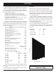
Installation & Operating Manual The Harman Clarity 929 DV Direct Vent Gas Stove “Ce manuel est disponible en Français sur demande” R10 This appliance may be installed in an aftermarket, permanently located, manufactured home (USA only) or mobile home, where not prohibited by local codes. This appliance is only for use with the type of gas indicated on the rating plate. This appliance is not convertible for use with other gases, unless a certified kit is used.
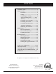
Contents INTRODUCTION...............................................3 INSTALLATION.................................................4 Clearances................................................4 Venting.....................................................5 Terminating the Venting.........................6 Approved Venting Parts................8-14 Assembly...........................................15 Connecting to a Gas Supply.................17 Connecting the Cordset........................
Introduction The Harman Clarity Direct Vent 929DV Gas Heater is a listed gas-fired direct vent room heater tested by Inchcape Testing/Warnock Hersey to standard ANSI Z21.88-2002CSA 2.33-2002, and CAN/CGA-2.17-M91. The installation of the Clarity Direct Vent Gas Heater must conform with local codes, or in the absence of local codes, with National Fuel Gas Code, ANSI Z223.1 — latest edition and CAN 1 B1-149.1 and .2 Installation Code. Also for use in mobile (manufactured) homes after home is sited.
Installation IMPORTANT NOTICE Due to high temperatures, the Clarity Direct Vent Gas Heater should be located out of traffic and away from furniture and draperies. Children and adults should be alerted to the hazards of high surface temperatures and should stay away to avoid burns or clothing ignition. Young children should be carefully supervised when they are in the same room as the appliance. Clothing or other flammable materials should not be placed on or near the Clarity Direct Vent Gas Heater.
VENTING The Clarity Direct Vent Gas Heater has been tested and is listed for installation with specific venting components. The venting manufacturer's warranty will be voided, and serious fire, health, or other safety hazards may result from any of the following actions: • Installation of any damaged venting component. • Unauthorized modification of the venting System. • Installation of any venting component not manufactured by an approved manufacturer.
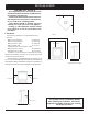
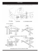
VENTING Requirements for Terminating the Venting WARNING: Venting terminals must not be recessed into a wall or siding.
VENTING These Diagrams, along with the table, detail the restrictions on the vent terminal location.
VENTING Use Only Approved Venting This appliance has been tested and is listed for installation only with specific venting components. The venting manufacturer's warranty will be voided, and serious fire, health, or other safety hazards may result from any of the following actions: • Installation of any damaged venting component. • Unauthorized modification of the venting system. • Installation of any venting component part not manufactured by the approved manufacturer.
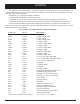
VENTING Simpson Dura-Vent Direct Vent GS Selkirk Direct-Temp Stock No.
VENTING 10 Secure Vent Direct Vent System - 4” x 6-5/8” and 5” x 8” Description Simpson Dura-Vent Direct Vent GS Secure Vent Stock No. Cat No. Length 6” (Galvalume).........................SV4L6 Length 6” (Black)................................SV4LB6 Length 12” (Galvalume).......................SV4L12 Length 12” (Black)..............................SV4LB12 Length 24” (Galvalume).......................SV4L24 Length 24” (Black)..............................
VENTING 11 Montigo Direct Vent Standard Series Direct Vent (4"/ 7") Description Order Code Horizontal Terminations 3" length, no mounting frame (use with MSR or MOSR) .................... MTO3 3" Termination, with integral mounting frame .................................... MTO3F Vertical Termination Termination for vertical installations ..................................................MVTK1 Includes MXT-10 adaptor (for straight, vertical installations) Termination Touch-Up Paint ....................
VENTING Montigo Direct Vent Standard Series Direct Vent (4"/ 7") Description Order Code Snorkel Terminations 18" vertical rise .............................................................................. SNK47-2 30" vertical rise ...............................................................................SNK47-3 Heat Guard Fits all Standard Series (4/7") terminations ........................................MTKOG Heat Shields Through-the-wall Radiation Shield for 4"/7" venting ...................
VENTING 13 Montigo Direct Vent Premium Series Direct Vent (5"/8") Description Order Code Horizontal Terminations 3" Termination with no mounting frame (male connector). ..................... PTO3 (use with MSR or MOSR). 3" Termination & mounting frame (male connector). ............................. PTO3F Vertical Termination Termination for vertical installations (male connector) ........................... PVTK1 Includes PXT-10 adaptor (for straight, vertical installations).
VENTING Montigo Direct Vent Premium Series Direct Vent (5"/8") Description Order Code Snorkel Terminations 18" vertical rise ......................................................................................SNK58-2 30" vertical rise ......................................................................................SNK58-3 Insulated Offset Box M38DV-ST offset box. Used only on the M38DV-ST when a shelf or T.V. stand is required above the fireplace. ..............................................
assembly Connecting To An Existing Chimney The Clarity may be connected to an existing masonry chimney by using a Simpson Dura-Vent conversion kit #934. With this kit and a 4" flex liner in the chimney, the flue gases exit through the 4" liner, and the outside air comes down the chimney, in the space between the chimney and the liner. This method allows you to install the Clarity using your chimney and still get the added efficiency provided by direct venting.
assembly Install the Center Log The center log goes all the way to the back and should be centered. When properly positioned, there should be an even gap along the front of the center burner in the cavity in the log. A small portion of the log support frame will be revealed. The center log has a round viewing port in the left end through which the pilot can be observed.
CONNECTING THE HEATER TO A GAS SUPPLY 17 Burn Only the Fuel for which the Heater is Equipped The Clarity Direct Vent is built for use with Propane but can be converted to burn Natural Gas.The label on the burner system module indicates the fuel for which it is equipped, and must be marked upon installation of the stove or conversion kit. A second label, located near the rating plate, also indicates the fuel type.
CONNECTING THE HEATER TO CORDSET Connecting the Cordset The Clarity Direct Vent Gas Heater must be installed in accordance with local codes or, in the absence of local codes, with the most recent edition of the National Electrical Code ANSI/NFPA 70, or the current Canadian Electrical Code C22.1. NOTE: The convection fan requires a 120 VAC supply for operation, but the heater can be operated without the fan as in the case of a power outage. Plug the 3-prong grounded electrical cord plug into the wall.
AIR SHUTTER ADJUSTMENT AIR SHUTTER ADJUSTMENT The final step of the installation is to check the flame Monitoring the Gas Flame pattern, which should resemble the pattern illustrated in the right column: The flames should be relatively well-defined and stable. They should be bright yellow with a blue base where attached to the burner ports, and should not look orange or sooty. Start the heater according to the directions, and allow the heater to burn for approximately 15 minutes.
OPERATION HOW TO LIGHT THE FIRE 1. STOP! Read the safety information on the left side of the panel on page 21. 2. If using the optional thermostat, set thermostat to the lowest setting. 3. Turn off electric power to the appliance. 4. Turn the ON-OFF/THERMOSTAT switch to the OFF position. 5. Push in the gas control knob slightly and turn it clockwise to "OFF." NOTE: The knob cannot be turned from "PILOT" to "OFF" unless it is pushed in slightly. Do not force it. 6.
Safety/lighting Label 21
MAINTENANCE A qualified service person recommended by your Harman dealer should conduct an annual inspection and maintenance of your Clarity, its venting, and the installation to keep it running safely and efficiently. The following procedures should be performed only by a qualified service person. The gas supply should be turned off whenever a maintenance procedure is performed.
wIRING dIAGRAM 23 Clarity Direct Vent Wiring Diagram The Clarity Direct Vent gas heater, when installed, must be electrically grounded in accordance with current local codes or, in the absence of local codes, with the current edition of National Electrical Code, ANSI/NFPA 70 in the United States or the current Canadian Electrical Code CSA 22.1 in Canada. WARNING: This heater is equipped with a three-pronged grounding plug that should be plugged directly into a properly grounded receptacle.
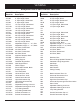
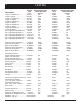
parts list 24 The following replacement parts for your Harman Clarity Direct Vent are available from your Harman dealer. ID# 1. 2. 3. 4. 5. 6. 7. 8. 9. 10. 11. 12. 13. 14. 15. 16. 17. 18. 19. 20. 21. 22. 23. 24. 25. 26. 27. 28. 29. 30. 31. 32. 33. 34. 35. 36. Part No.
parts 25 3 58 59 49 17 21 16 52 50 18 17 63 53 55 51 16 27 17 56 62 57 61 24 64 1 54 60
Clarity Burner Module : Exploded View 26 36 47 38 14 13 12 53 52 33 32 39 31 48 41 42 40 46
Specifications 27 Clarity Direct Vent 929DV Gas Heater Tested to ANSI Z21.88-2002, CSA 2.33-M02, and CAN/CGA 2.17-M91. Input Rating (Btu/hr) (0-4500 ft) (0-1375 m) Min. Input Rating (Btu/hr) (0-4500 ft) (0-1375 m) Injectors (DMS) (front/middle/rear) (0-4500 ft) (0-1375 m) Manifold Pressure (in w.c./kPa) Minimum Manifold Pressure (in w.c./kPa) Minimum Inlet Pressure (in w.c.
APPENDIX a 28 Converting the Clarity Direct Vent from One Gas to Another in the Field NOTE: THE CONVERSION SHALL BE CARRIED OUT IN ACCORDANCE WITH THE REQUIREMENTS OF THE PROVINCIAL OR LOCAL AUTHORITIES HAVING JURISDICTION AND IN ACCORDANCE WITH REQUIREMENTS OF THE CURRENT EDITION OF THE NATIONAL FUEL GAS CODE, ANSI Z223.1 or the CAN/CGA-B149 INSTALLATION CODES.
APPENDIX b 29 De-rating for High Altitude For U.S. installations, the Clarity Direct Vent is approved for elevations up to 2000 feet using the factory-installed burner injectors. At elevations above 2000 feet, U.S. codes require a decrease in the input rating by changing the burner injectors to a smaller size. The chart below lists by part numbers the appropriate injectors for both LP and natural gas at various altitudes.