
Specifications

Page 9
G0204
Panorama Direct Vented Fireplace
Installation
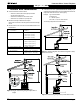
Wiring
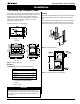
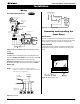
Figure 15b. Fan wiring schematic.
Gas Control and Pilot Wiring
Honeywell (Q3450)
Pilot Assembly
Pilot Electrical
Harness Connector
Honeywell Gas
Control (SV9501M)
Gas Control
Connector
Fuse
Limit
Switch
Wall
Switch
Fan Plug
Receptacle
Junction Box
Junction Box Cover
White
Black
Green
40 VA
Transformer
115VAC
24VAC
Grnd Screw
Figure 14. Wiring for the M38DV-PRC-I with Honeywell gas control
and pilot.
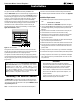
Figure 15a. Fan wiring.
NOTE: If any of the original wire supplied with the
appliance is replaced, it must be replaced with the
same type, or its equivalent.
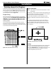
Fan Wiring
The M38DV-PRC is equipped with 4 fans for circulating heat into the
living space. Installations in Canada must be in accordance with CSA
C22.1 Canadian Electrical Code Part 1 and/or Local Codes.
Installations in the USA must be in accordance with local codes or, in
the absence of local codes, with the National Electrical Code, ANSI/
NFPA 70-1987.
Fan Switch
M38DV-PRC-I
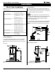
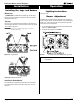
Removing and Installing the
Inner Doors
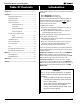
Door Removal
The inner (combustion) doors are located behind the outer decorative
doors. To remove the inner doors, simply unscrew the nine (9) machine
screws on the top, bottom and side of the door. (See figure 16).
Door Installation
To attach the inner doors, align the door with the screw holes and re-
fasten with all nine machine screws. Ensure that a good seal is main-
tained.
Figure 16. Removing inner doors.
115/1/60 Supply
G L1 L2
Fan Switch
G
L2-WH
L1-BLK
Quick Connect
plug to motor
Fan Motors (4)