
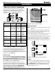
Specifications
Page 13
P/N XG0205
M40DV-PFC Peninsula Gas Fireplace
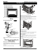
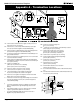
Wiring
Gas Control and Pilot Wiring
Honeywell (Q3450)
Pilot Assembly
Pilot Electrical
Harness Connector
Honeywell Gas
Control (SV9501M)
Gas Control
Connector
Fuse
Limit
Switch
Wall
Switch
Fan Plug
Receptacle
Junction Box
Junction Box Cover
White
Black
Green
40 VA
Transformer
115VAC
24VAC
Grnd Screw
Figure 21. Wiring for the M38DV-PFC-I with Honeywell gas control
and pilot.
M40DV-PFC-I
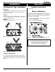
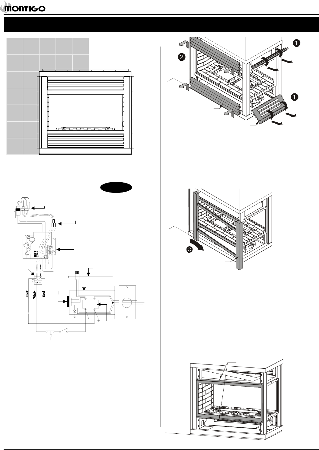
Removing and Installing the
Glass Doors
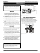
Removing the Louvres and Side Panels
Rotate the upper end louvre assembly approximately 110° (as shown in
figure 22a, step ). Pull the assembly towards you to remove it from
the fireplace.
Repeat this for the lower end louvre assembly.
Remove the louvre assemblies (upper and lower) from one side of the
fireplace. Grasp the assembly underneath one of the louvres and up
slightly and pull outwards, as shown in figure 22a.
Remove the side panel by sliding it out and away from the back of the
fireplace. Refer to figure 22b.
Side louvre
assembly
End louvre
assembly
Figure 22a. Removing the louvre assemblies.
Figure 22b. Removing the side panel.
Side panel
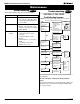
Removing the Doors
To remove the inner doors, simply unscrew the eight (8) machine
screws on the top and bottom of the door. (See figure 22c).
Door Installation
To re-install the doors, align the door with the screw holes and re-
fasten with all eight machine screws. Ensure that a good seal is
maintained.
Re-install the side panels and louvre assemblies by reversing the
above steps.
Figure 22c. Removing the door.
8 Screws
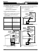
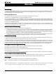
Installation
Figure 20c. When using a tile surround, do not tile over the outside frame.