
Owner`s manual


Page 8
L42DF Flush Indoor Gas Fireplace
Part No. XG0181 - 081009
f i r e f e a t u r e
Installation
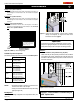
Example A: (Acceptable Installation)
If the vertical dimension from the hearth is 84" and the horizontal run to
the wall flange of the vent termination is 36", this would be an acceptable
installation.
Example B: (Acceptable Installation)
If the vertical dimension from the hearth is 90" and the horizontal run to
the wall flange of the vent termination is 126", this would be an acceptable
installation.
Example C: (Unacceptable Installation)
If the vertical dimension from the floor of the fireplace is 74" and the
horizontal run to the wall flange of the vent termination is 108", this would
NOT be an acceptable installation.
Figure 9b. L42DF Top Vent Venting Graph
Available Top Vent Components
The following venting components are available for the L42DF Top Vent:
5" / 8" Venting
A - Termination PTO-3(3"Length)
PTO-3F(3"Length)
B - Stucco Kits MSR (Stucco Frame)
MOSR (Stucco Can)
BSR ( Brick Can)
C - Flex Sections PFL-1(12"Section)
PFL-2(24"Section)
PFL-3(36"Section)
PFL-4(48"Section)
D - Rigid
Sections
PEXT-1(12"m/fSection)
PEXT-2(24"m/fSection)
PEXT-3(36"m/fSection)
PEXT-4(48"m/fSection)
E - Elbows PEL-90MM (m/m 90° Elbow)
PEL-90FF (f/f 90° Elbow)
PEL-90FM (f/m 90° Elbow)
NOTES: All dimension lengths for vertical or horizontal runs are
measured from centre of the vent pipe.
Venting runs must fall within the limits set by the venting
graph (see Figure 9A).
Example 1:
ForourshortestventingcongurationusecomponentsAandE(see
Figure 10).
Figure 10. Typical Top Vent installation. If the 90° elbow is installed
directly on the replace, for height to the center of the
termination see chart on page 3.
Important:
Aninspectionoftheexplosionreliefappersanddoormustbe
madepriortolightingthereplace.Thiswillensurethedoorgas-
keting material will provide an adequate seal during operation.
Figure 11. Corner installation.
Example 2:
45° Corner Installation. (Only available using Top Vent.)
AttachaPEL-90(90°elbow)directlyontotheuecollar,andattach
it to the PEL-45 (45° elbow). Cut the PXT-18 to suit and insert it into
thePEL-45.Slidethereplaceintoposition,andthenconnectitto
the exterior termination.
PEL-45 Elbow
PEL-90 Elbow
PXT-18
Important: Corner Installation is available Only for
L42DF Top Vent Units.
PEL
Power Vent models, LDVPV47
EDVRSPV58, and EDVWSPV58
to be used within the shaded area of
graph. (See Index of this guide for
applicable Product page).