
Owner`s manual


Page 7
L42DF Flush Indoor Gas Fireplace
Part No. XG0181 - 081009
f i r e f e a t u r e
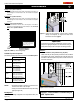
Figure 6c. Installing the Nailing Flange Extension.
Installation
Converting to Top Vent/ Rear Vent
L42DF Top Vent
Use the following instructions to convert a L42DF, for Top Vent use:
1. Installthe5"inneruecapontherearueoutletandsecurethe
capinplacewithvescrews,asshowningure7a.
2. Installthe8"outeruecapontherearueoutlet,andsecureit
withvescrews,asshowningure7a.
3. Installtheuegasketmaterialanduecoverplateontherearvent
outlet . Fasten the plate with four screws, as illustrated below.
4. Installthe5"inneruecollarandthe8"outeruecollarinplace
on the top vent outlet using 5 screws, as illustrated below.
L42DF Rear Vent
Figure 7a. Flue cap installation, Top Vented L42DF replace.
Figure 7b. Flue collar installation, Top Vented L42DF replace.
Figure 8a. Flue cap installation, Rear Vented L42DF replace.
Figure 8b. Flue collar installation, Rear Vented L42DF replace.
Use the following instructions to convert a L42DF, for Rear Vent use:
1. Installthe5"inneruecaponthetopueoutletandsecurethe
capinplacewithvescrews,asshowningure8a.
2. Installthe8"outeruecaponthetopueoutlet,andsecureit
withvescrews,asshowningure8a.
3. Installtheuegasketmaterialanduecoverplateonthetop
vent outlet. Fasten the plate with four screws, as illustrated in
gure8b.
4. Installthe5"inneruecollarandthe8"outeruecollarinplace
on the rear vent outlet using 5 screws, as illustrated below.
Top Vent Venting Runs
For the L42DF Top Vent, there are two types of installations: A) Through-
The-Wall Installations and B) Vertical (Through-The-Roof) Installations.
A) Through-The-Wall Installations
Before you install any venting, you must determine whether the venting
runwillbeacceptable.Unacceptableventingcanaffectthereplace's
combustion.
The Venting Graph
Measuretheverticalheightfromthereplacehearthtothecentreof
theterminationandthehorizontalrunfromthereplaceuecollarto
thewallangeofthetermination.PlotontheVentingGraph(Fig.9a)
with an 'X'.
If the 'X' falls on or above the top boundary of the shaded area, the
installation is acceptable.
5” Inner Flue Cap
8” Outer Flue Cap
Flue Gasket
Flue Cover Plate
8” Outer Flue Collar
5” Inner Flue Collar
5” Inner Flue Collar
8” Outer Flue Collar
Flue Gasket
Flue Cover Plate
5” Inner ue CapFl
Fl8” Outer ue Cap
Installing the Nailing
Flange Extension
Oncethereplaceisplacedintotheroughframedopening,andthe
supplied steel lintel is in place, (Part No. L42087) (see Figure 2),
the supplied nailing extension must be placed along the top edge of
thereplaceandsecurelyfastenedinplacetothemetallintel,and
combustiblewoodframing.Note:Thenailingangeextensioncanbe
substituted with a piece of NON-Combustible material of the same
size and thermal characteristics, ie: cement board or equivilent.