
Owner`s manual


Page 4
L42DF Flush Indoor Gas Fireplace
Part No. XG0181 - 081009
f i r e f e a t u r e
Installation
Installing The Fireplace Shell
Thereplacemaybeinstalledinanylocationthatmaintainsproperclear-
ances to air conditioning ducts, electrical wiring and plumbing. Safety,
aswellasefciencyofoperation,mustbeconsideredwhenselecting
thereplacelocation.Trytoselectalocationthatdoesnotinterfere
withroomtrafc, hasadequateventilation,andoffersanaccessible
pathway for Direct Vent installation. Refer to page 4 - Vent Installation
for more information.
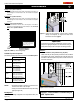
Thereplacedimensionsareshownbelow:
When installing a shelf over the top of the replace, the following
guidelines must be adhered to: For Rear Vent applications the
minimumclearancefromthetopofthereplacetoshelfframingis10".
ForTopVentapplications,the minimum clearanceis 21".(Minimum
2" clearance must still be maintained around the vent pipes.)
Top Vent
Figure 2. Framing dimensions.
* When sheetrock is
not used behind the
fireplace, framing
depth may be reduced
by 5/8"
Framing
Top View
Front View Side View
* Clearance from the top of the replace to a combustible ceiling
within the replace enclosure.
** Refer to graph and requirements on Page 11.
Unprotectedcombustiblewallswhichareperpendiculartothereplace
opening, must not project beyond the shaded area shown in Figure
24.
For protection against freezing temperatures, it is recommended that
outer walls of the chase be insulated with a vapor barrier. This will reduce
thepossibilityofacold-airconvectioncurrentonthereplace.
Figure 1. Fireplace dimensions.
Rear Vent
Clearances:
The clearances apply to all dimensions except the framed opening,
where the clearnace to combustibles is 0". The L42DF clearances to
combustible materials are:
5 1/2”
5 1/4”
19 3/4”
30 1/2”
1 1/4”
1”
33”
5”
8”
26 5/8”
19 3/4”
39 1/2”
1 1/4”1 1/4”
39 1/2”
5”
8”
13”
42”
22 5/8”
42”
36 1/2”
84 7/8
0" clearance
to corners only
42
60 5/8”
L42DF
Top - Rear Vent *
10"
Top - Top Vent
21"
Back
2"
Sides
1"
Floor
0"
Mantle**
6"
WARNING!
When this appliance is installed directly on carpeting, tile or any
combustiblematerialotherthanwoodooring,itmustbeinstalled
on a metal or wood panel extending the full width and depth of
the appliance.
Figure 3. Minimum Corner framing
dimensions, using a 45°.
40 1/2
21
36 1/2
MEL Short
90 elbow
shelf
Framing
/ Hea
der,
supplied shield
33
Figure 4. Framing for shelves over the replace, (Combustible materials).
Figure 3a. Top Vent
or Rear Vent
(with Non-
Combustible materials).
MIN
84”
to
96”
Header
7”
3”
MIN
1”
C
ieling
Floor
Alcove
area over
Fireplace
Top
Vent
Non-Combustible
Materials Only
Rear
Vent
12” Max.
36 1/2
10
33
Framing / Header,
supplied shield
shelf
Rear
Vent
12” Max.