
Installation guide

Page 3
L-Series DF Gas Fireplace
Part No. XG0180
f i r e f e a t u r e
Installation
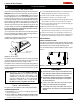
Installing The Fireplace Shell
The replace may be installed in any location that maintains proper clear-
ances to air conditioning ducts, electrical wiring and plumbing. Safety,
as well as efciency of operation, must be considered when selecting
the replace location. Try to select a location that does not interfere
with room trafc, has adequate ventilation, and offers an accessible
pathway for Direct Vent installation. Refer to page 4 - Vent Installation
for more information.
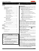
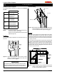
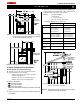
The replace dimensions are shown below:
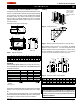
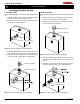
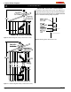
When installing a shelf over the top of the replace, the following
guidelines must be adhered to: For Rear Vent applications the
minimum clearance from the top of the replace to a shelf is 9". For
Top Vent applications, the minimum clearance is 17 1/2". (Minimum
2" clearance must still be maintained around the vent pipes.)
Figure 4. Framing for shelves over the fireplace.
Top Vent
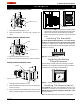
Figure 3. Minimum Corner framing dimensions, using a 45° elbow.
Figure 2. Framing dimensions.
* When sheetrock is
not used behind the
fireplace, framing
depth may be reduced
by 5/8"
Framing
WARNING:
When this appliance is installed directly on carpeting, tile or
any combustible material other than wood ooring, it must be
installed on a metal or wood panel extending the full width and
depth of the appliance.
Top View
Front View
Side View
Unprotected combustible walls which are perpendicular to the replace
opening, must not project beyond the shaded area shown in Figure
24.
For protection against freezing temperatures, it is recommended that
outer walls of the chase be insulated with a vapor barrier. This will reduce
the possibility of a cold-air convection current on the replace.
Figure 1. Fireplace dimensions.
Rear Vent
M
N
O
N
P
Q
0" clearance
to corners only
R
R
M
N
O
N
P
Q
0" clearance
to corners only
R
R
M
N
O
N
P
Q
0" clearance
to corners only
R
R
M
N
O
N
P
Q
0" clearance
to corners only
R
R
M
N
O
N
P
Q
0" clearance
to corners only
R
R
A B C D E F G H I J K L
L38DF
37
3
/
4 29
1
/
2 34
3
/
4 1
1
/
4 18
1
/
4 1 18
1
/
2 35
3
/
4 11
1
/
2 5 8 21
3
/
4
L42DF
42 30
1
/
2 1
1
/
4 18
1
/
2 1
27
12
1
/
2 5 8
L52DF
52 33
1
/
4 47 2
1
/
2 21
1
/
4 1 22
1
/
2 49
1
/
4 13
1
/
2 5 8 26
1
/
2
38
7
/
8
19
3
/
4 39
1
/
2
M
T
10
S
V
Header
Header
Shelf
MEL Short
Shelf
L
M
5
1
/
2
Header
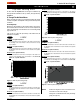
combustible materials are:
L38DF L42DF L52DF
Top - Rear Vent *
9" 9" 9"
Top - Top Vent
17
1
/
2" 21" 17
1
/
2"
Back
1" 2" 1"
Sides
1" 1" 0"
Floor
0" 0" 0"
Mantle**
4" 6" 4"
Clearances
These clearances apply to all dimensions except the framed opening,
where the clearance to combustibles is
0". The L-Series clearances to
* Clearance from the top of the to a combustible ceiling within the
enclosure.
** Refer to page 14.
M
O Q S
L38DF
35
1
/
4 38 20
1
/
8 75 54
1
/
4 4
1
/
4 29 38
1
/
2
L42DF
36
1
/
2 22
5
/
8 82 58
5
/
8 4
1
/
4 33
L52DF
39 52 23
1
/
2 96
1
/
2 68
1
/
4 4
1
/
4 35
1
/
8 48
41
1
/
2
43
1
/
2
7
/
8
T
N P
R
17
N/A
21
V