fire feature Installation Operation & Maintenance L-Series DF Gas Fireplace L38DF L42DF L52DF Safety Notice: Glass doors on gas fireplaces are extremely hot while the fireplaces is on and remain hot even after the fireplace has been turned off. Safety screens are available and can reduce the risks of severe burns. Please keep children away from the fireplace at all times. Warning: Improper installation, adjustment, alteration, service or maintenance can cause injury or property damage.
L-Series DF Gas Fireplace fire feature Table Of Contents Introduction Introduction .............................................................................. 2 Thank You for choosing a Montigo Gas Fireplace. Installation About this Fireplace: Installing and Framing the Fireplace............................... 3 Installing the Gasline....................................................... 4 Vent Installation...............................................................
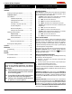
L-Series DF RGas Fireplace fire feature Installation Installing The Fireplace Shell The fireplace may be installed in any location that maintains proper clearances to air conditioning ducts, electrical wiring and plumbing. Safety, as well as efficiency of operation, must be considered when selecting the fireplace location. Try to select a location that does not interfere with room traffic, has adequate ventilation, and offers an accessible pathway for Direct Vent installation.
L-Series DF Gas Fireplace fire feature Installation Installing The Gas Line The gas line must be installed before finishing the L-Series DF Fireplace. Natural Gas requires a minimum inlet gas supply pressure of 5.5" W.C. & a manifold pressure of 3.5" W.C. Propane Gas requires a minimum inlet gas supply pressure of 11" W.C. & a manifold pressure of 10" W.C. Provision must also be made for a 1/8" N.P.T.
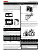
L-Series DF Gas Fireplace fire feature Installation Installing Terminations with Built-In Frames Installing Heat Guards over Terminations 11 PTO-3F (5"/8") 11 PTKOG (5"/8") 1. Frame the termination opening to 11" x 11". 2. Fasten the termination to the studs using a minimum of 4 screws. Installing Terminations with MSR Frames 12 1. Ensure that the two long mounting brackets are facing the bottom of the termination. (See inset).
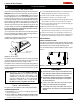
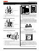
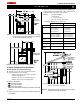
L-Series DF Gas Fireplace fire feature Installation Converting to Top Vent/ Rear Vent L-Series DF Top Vent Use the following instructions to convert an L-Series DF for Top Vent use: 1. Install the 5" inner flue cap on the rear flue outlet and secure the cap in place with five screws, as shown in figure 7a. 2. Install the 8" outer flue cap on the rear flue outlet, and secure it with five screws, as shown in figure 7a.
L-Series DF Gas Fireplace fire feature Installation Top Vent Venting Runs For the L-Series DF Top Vent, there are two types of installations: A) Through-The-Wall Installations and B) Vertical (Through-The-Roof) Installations. Example C: (Unacceptable Installation) If the vertical dimension from the floor of the fireplace is 74" and the horizontal run to the wall flange of the vent termination is 108", this would not be an acceptable installation.
L-Series DF Gas Fireplace fire feature Installation Available Top Vent Components The following venting components are available for the L-Series DF Top Vent: Horizontal Venting 90° Elbow 5" / 8" Venting A - Termination PTO-3 (3" Length) PTO-3F (3" Length) B - Stucco Kits MSR (Stucco Frame) MOSR (Stucco Can) BSR ( Brick Can) C - Flex Sections PFL-1 (12" Section) PFL-2 (24" Section) PFL-3 (36" Section) PFL-4 (48" Section) Termination PEXT Section D - Rigid Sections PEXT-1 (12" m/f Section) PEXT
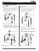
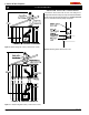
L-Series DF Gas Fireplace fire feature Installation A maximum of two offsets (each offset has two 90° bends) may be made and shall not exceed total length of 25% of the vertical vent height, when measured center to center of piping. Example: Typical vent installation. 20' vertical vent 2 - 2' offsets required 25% of 20' = 5' max. offset allowed This venting configuration meets requirements. 4" / 7" Venting Figure 13. Retracted Installation using a combination of solid and flex venting.
L-Series DF Gas Fireplace fire feature Installation Reduced Vertical Installation It is possible to reduce vertical vent runs from 5"/8" venting to 4"/7" venting. Reduced vertical venting may only be used when the installation exceeds 12 feet and terminates through the roof, and if the vertical vent reducer is used with the following venting configuration. Figure 16. Vertical venting with 1 offset (1 offset= two 90° bends). Figure 18. Reducing Vertical Vent from 5/8" to 4/7". Figure 17.
L-Series DF Gas Fireplace fire feature Installation Rear Vent Venting Runs The L-Series DF Rear Vent has three possible installations which do not require vertical lift, all of these installations require that you install the RHS101 heat shield. Heat Shield 2. 45° Corner Installation. Attach an PEL-90 (90° elbow) directly onto the flue collar, and attach it to the PEL-45 (45° elbow). Cut the PXT-18 to suit and insert it into the PEL-45.
L-Series DF Gas Fireplace fire feature Installation B. Multi-Elbow Installations For more difficult installation situations, the L-Series DF Rear Vent may be installed with two - 90° elbows and up to 15' of horizontal run.
L-Series DF Gas Fireplace fire feature Installation Installation Of Rear Vent DV The following venting components are available for an L-Series DF in a Rear Vent installation: 4" / 7" Venting Figure 22c. L52DF Multi-Elbow Venting Graph.
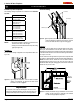
L-Series DF Gas Fireplace fire feature Installation Finishing Around the Fireplace Surround Heat Shield Combustible mantels and mouldings may be safely installed over the top and on the front of the fireplace provided that they do not project beyond shaded area shown in Figure 24. Side wall clearances are 3". Combustible surrounds may be installed with 3" clearance to the side of the fireplace as shown in Figure 25.
L-Series DF Gas Fireplace fire feature Installation Wiring Gas Control and Pilot Wiring 5/1/60 Supply G L1 L2 L-Series DF-I Honeywell (Q3450) Pilot Assembly Pilot Electrical Harness Connector Honeywell Gas Control (SV9501M) Figure 27b. Wiring schematic for optional fans. Gas Control Connector Junction Box Cover Fuse Removing and Installing the Door Junction Box Fan Plug Receptacle Black White Green 115VAC 24VAC Gnd Screw 40 VA Transformer Limit Switch Wall Switch Figure 26.
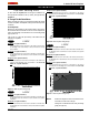
L-Series DF Gas Fireplace fire feature Operation - Model L-Series DF L-Series DF with Continuous Pilot For Your Safety - READ BEFORE LIGHTING: WARNING: If you do not follow these instructions exactly, a fire or explosion may result causing property damage, personal injury or loss of life. A. This appliance has a pilot which must be lighted by hand. When lighting the pilot, follow these instructions exactly. B. BEFORE LIGHTING smell all around the appliance area for gas.
L-Series DF Gas Fireplace fire feature Operation - Model L-Series DF-I L-Series DF-I with Honeywell Electronic Ignition For Your Safety - READ BEFORE LIGHTING: WARNING: If you do not follow these instructions exactly, a fire or explosion may result causing property damage, personal injury or loss of life. A. This appliance is equipped with an ignition system that lights the pilot burner automatically. Do not attempt to light the pilot by hand. B.
L-Series DF Gas Fireplace B-Series BF-A L-Series DF-I fire feature Operation - Model L-Series DF-A with American Flame Electronic Ignition with American For Your Safety - Flame READ Electronic BEFORE Ignition LIGHTING: WARNING: If you do not follow these instructions exactly, a fire or explosion may result causing property damage, personal injury or loss of life. A.
L-Series DF Gas Fireplace fire feature Operation Maintenance Lighting Instructions General See pages 16, 17 and 18. Burner Adjustment The L-Series DF is equipped with an adjustable burner, allowing you to raise or lower the flames. To adjust the flames, locate the black knob marked 'Hi-Lo', in the centre of the gas control valve (See Figure 32). The front burners are not adjustable. To raise the flame height, turn the black knob (located behind the lower trim) counter-clockwise.
L-Series DF Gas Fireplace fire feature Maintenance Gas Control Valve Troubleshooting L-Series DF-I Power Generator Pilot Adjustment Screw Wall Switch Inlet Pressure Manifold Pressure Test Connection Figure 33. Sit Nova 820 gas valve. Pilot Burner Adjustment 1. Locate Pilot Adjustment Screw. (See figure 33.) 2. Adjust pilot screw to provide properly sized flame as shown in figure 34). 3. After installing or servicing, leak test with a soap solution with main burner on.
L-Series DF Gas Fireplace fire feature Warranty The Warranty The Companies warrants the Montigo Gas Appliance to be free from defects in materials and workmanship at the time of manufacture. On the Montigo, there is a ten-year warranty on the firebox and its components, a five-year warranty on the main burner and pilot burner, and a one-year warranty on the gas control valve and fibre logs. Glass, plated/painted finishes, and refractory lining are exempt.
L-Series DF Gas Fireplace fire feature Appendix A - Termination Locations A = clearance to the termination frame above grade, veranda, porch, deck, or balcony [16 inches (41 cm) minimum] N= B = clearance to door, or sides and top of window, that may be opened [16 inches (41 cm) minimum for appliances ≤100 000 BTU/H (30kW)] P = clearance under veranda, porch, deck, or balcony [16 inches (41 cm) minimum‡ to non-combustibles] [22 inches (56 cm) minimum‡ to combustibles] C = clearance to bottom of window
L-Series DF Gas Fireplace fire feature Maintenance Notes Spare Parts - L-SeriesDF L38DF L42DF NG Gas Valve RGC1006 RGC1006 LP Gas Valve RGC1005 RGC1005 NG Pilot RPA020 RPA020 LP Pilot RPA021 RPA021 Burner NG RBL3801 RBL4201 Burner LPG RBH3802 RBL4202 ROR1151 ROR1153 ROR1152 ROR1154 RDTL38 RDTL42 N/A N/A RLG549 RLG550 Door Log Set Log Base Part No.
XG0180 - 033007 Canadian Heating Products Inc. Montigo Del Ray Corp.