
Owner`s manual


Page 9
L42DF-ST See-thru Indoor Gas Fireplace
Part No. XG0812 - 081009
f i r e f e a t u r e
Short Congurations:
For installations straight through the wall, use an PTO-3/-3F termina-
tion and PXT-5 or PXT-10 to achieve the desired length. The maxi-
mumhorizontalventrunwithnoverticalliftis12".SeeFigure16.
Heat Shields
Duetohighuetemperatures,theheatshield(RHS101)mustbe
used on all installations straight through the wall, at the point
where the vent pipe connects to the termination. With the heat shield,
ventclearancescanbemaintainedat1".Theheatshieldisnot
includedwiththereplace.
Example:
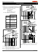
A 10' section of rigid pipe and a 90° elbow may be used in conjunc-
tion with a 3 ft. flex section (PFL-3) will, when extended in a chase,
allow for a maximum horizontal run of twelve and one-half feet from
the centre of the fireplace to outside wall and a minimum of 7'6" when
retracted in opposite direction. (See Figure 16.)
Long Vent Runs:
For longer or more complex vent runs, vertical lift is required. First
ensure that the planned run is acceptable using the Vent Graph. Plan
out the required components using the chart above. You may be able
to use fewer components using the chart on Page 8.
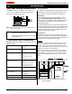
Figure 16. Extended horizontal installation using a combination of
rigid and ex venting.
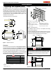
To install the heat shield, slide one section over the vent pipe on the
inside of the wall opening, with the circular portion inside the wall cav-
ity. Screw the shield in place over the wall opening. Install the second
section on the outside of the wall opening sliding the circular portion
into the wall opening. Refer to Figure 15.
Horizontal Vent Installation
Vent systems that terminate through a wall may comprise up to seven
different components:
A - Termination PTO-3
PTO-3F
B - Stucco Kits MSR (stucco frame)
MOSR (stucco can)
D - Flex sections PFL-1 (12" section)
PFL-2 (24" section)
PFL-3 (36" section)
PFL-4 (48" section)
E - Rigid sections PEXT-1 (12" section)
PEXT-2 (24" section)
PEXT-3 (36" section)
PEXT-4 (48" section)
F - Extensions PXT- 5 (5" section)
PXT-10 (10" section)
G - 90° elbow PEL-90F/F
PEL-90M/M
H - Heat Shield RHS101 ( for 5"/8" venting)
I - Heat Shield RHS 8 (for Top Venting)
"D" flex sections and "E" solid sections may be used in conjunction
with one another to obtain different possible horizontal length instal-
lations. NOTE: Flex section must not exceed maximum horizontal
length of 3 feet, and for this application the top clearance is to the
ceiling.
Installation
RHS8
NOTES: All dimension lengths for vertical or horizontal runs are
measured from centre of the vent pipe.
Venting runs must fall within the limits set by the venting
graph (see Figure 7b).
Side Vent Venting Requirements
The L42DF-ST can Only be rear vented as shown in Figure 15, 16,
17,17a,17b.TheventMustexitthereplaceusinga90degree
elbow and run vertical through the roof, etc.
Figure 15. Side Venting of L42-ST. (Must be as shown in Figure 15,
16, 17, 17a, and 17b.)