
Owner`s manual


Page 8
L42DF-ST See-thru Indoor Gas Fireplace
Part No. XG0812 - 081009
f i r e f e a t u r e
Installation
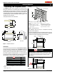
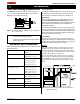
Figure 10. Straight, vertical venting showing required PXT-10 adaptor
(supplied with the PVTK-1 termination).
* For venting MIN 1" clearance to all vertical combustibles,
MIN 2" to all horizontal combustibles.
Figure 11. Vertical venting with 1 oset (1 oset= two 90° bends).
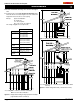
Figure 12. Vertical venting with 2 osets (1 oset= two 90° bends).
* For venting with four 90° a restrictor may need to be used. (PEXT
5/8 Vent).
C - Rigid Sections PEXT-1(12"m/fSection)
PEXT-2(24"m/fSection)
PEXT-3(36"m/fSection)
PEXT-4(48"m/fSection)
D - Support Ring
&Plate
PSPXT-8
E - Firestop PS-8
F - Roof Flashing PRF-7 (1/12 - 7/12 pt.)
PRF-7 (7/12 - 12/12 pt.)
G - Adaptor / Vent
Reducer
PVA5487(5"/8"to4"/7")
5" / 8" Venting
A - Termination PVTK-1
B - Flex Sections PFL-1(12"Section)
PFL-2(24"Section)
PFL-3(36"Section)
PFL-4(48"Section)
PEXT
Note: Flame characteristics will change if the maximum vent height is
used.
A maximum of two offsets (each offset has two 90° bends) may be
made and shall not exceed total length of 25% of the vertical vent
height, when measured center to center of piping.
Example: Typical vent installation.
20' vertical vent
2 - 2' offsets required
25% of 20' = 5' max. offset allowed
This venting configuration meets requirements.