
Owner`s manual


Page 6
L42DF-ST See-thru Indoor Gas Fireplace
Part No. XG0812 - 081009
f i r e f e a t u r e
Installation
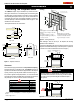
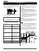
Installing Terminations with Built-In Frames
Installing Terminations with MSR Frames
12
12
1. Frametheterminationopeningto12"x12".
2. Fasten the termination to the studs using a minimum of 4 screws.
11
11
1. Frametheterminationopeningto11"x11".
2. Fasten the termination to the studs using a minimum of 4
screws.
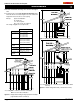
Installing Terminations with MOSR Frames
1212
12
MOSR
1. Frametheterminationopeningto12"x12".
2. Fasten the MOSR frame to the interior side of the studs using a
minimum of 4 screws.
3. Insert the termination into the MOSR frame as shown here, and
attach by screwing through the four pilot holes in the termination.
MSR
PTO-3 (5"/8")
PTO-3 (5"/8")
PTO-3 (5"/8")
PTKOG (5"/8")
1. Ensure that the two long mounting brackets are facing the bottom
of the termination. (See inset). This will provide more heat protection
at the top of the termination, where temperatures are highest.
2. Attach to the faceplate of the termination using four sheet metal
screws.
Installing Heat Guards over Terminations
Installing the Nailing
Flange Extension
Oncethereplaceisplacedintotheroughframedopening,andthe
supplied steel lintel is in place, (Part No. L42087) (see Figure 2),
the supplied nailing extension must be placed along the top edge of
thereplaceandsecurelyfastenedinplacetothemetallintel,and
combustiblewoodframing.Note:Thenailingangeextensioncanbe
substituted with a piece of NON-Combustible material of the same
size and thermal characteristics, ie: cement board or equivilent.
CAUTION:
Do not obstruct, or attempt to conceal, the vent termination.
These actions will affect the operation of the fireplace, and may
be hazardous.
In heavy snow areas, take extra care to prevent snow buildup
from obstructing the vent termination.
Figure 5a. Installing a PTO termination.
Figure 5b. Installing a PTO termination with the MSR frame.
Figure 5c. Installing a PTO termination with the MOSR frame.
Figure 5d. Installing a PTO termination heat guard.
Figure 6. Installing the Nailing Flange Extension.