
Owner`s manual


Page 5
L42DF-ST See-thru Indoor Gas Fireplace
Part No. XG0812 - 081009
f i r e f e a t u r e
Installation
Cautions:
Q Vent terminations can be very hot. If the termination is less
than7feetaboveapublicwalkway,itshouldbettedwith
acertiedMontigoHeatGuard.(Partno.PTKOG).
Q Do not obstruct, or attempt to conceal, the vent termination.
Theseactionswillaffecttheoperationofthereplace,
and may be hazardous.
Q In heavy snow areas, take extra care to prevent snow
buildup from obstructing the vent termination.
Q Use Montigo VSS Vinyl Heat Shield when using on
applications with vinyl siding to guard against possible
damage.
Installing The Gas Line
The gas line must be installed before completing the installation of the
L42DF-ST Fireplace. Natural Gas requires a minimum inlet gas supply
pressureof5.5"W.C.&amanifoldpressureof3.5"W.C.Provisionmust
alsobemadefora1/8"N.P.T.pluggedtappingandbeaccessiblefor
test gauge connection immediately upstream of the gas supply controls
totheappliance.Thereplacegasconnectionandthemainoperating
gas valve is located behind the removable trim at the bottom of the unit
andneedonlybeattachedtothegaslinewithanapprovedtting,as
required by the applicable installation codes.
•Onlyusegasshut-offvalvesapprovedforusebythestate,province,
region, or governing body, in which the appliance is being installed, or
as required by the applicable installation codes.
•Flexiblegasconnectorsmustnotexceed3feetinlength,unlessitis
allowable within applicable installation codes.
The appliance and its individual shut-off valve must be disconnected
from the gas supply piping system during any pressure testing of that
system at test pressures in excess of 1/2 psig (3.5 kPa).
The appliance must be isolated from the gas supply piping system by
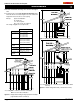
Note: After gas line is connected, each appliance connection,
valve and valve train must be checked while under normal
operating pressure with either a liquid solution, or leak
detection device, to locate any source of leak. Tighten any
areas where bubbling appears or leak is detected until
bubbling stops completely or leak is no longer detected.
DO NOT use a flame of any kind to test for leaks.
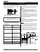
Figure 4. Gas line access.
closing its individual manual shut-off valve during any pressure testing
of the gas supply piping system at test pressures equal to or less than
1/2 psig (3.5 kPa).
Vent Installation
This section covers the installation of direct venting and terminations.
Installation Requirements
Q L42DF-ST fireplace is certified for use with Montigo Standard Series (5" /
8") venting components.
Q Minimum clearance to combustible construction around the vent pipe
is 1" on all sides, except on horizontal venting where the top of the pipe
must have a clearance of at least 2".
Q Use only certied Montigo vent components. (Use of other parts will void the
Montigo warranty, and may impede the operation of the fireplace.)
Q All joints must be secured with a minimum of two screws per joint
Q Vent terminations must not be recessed in walls or siding
Q Horizontal runs must be supported by a minimum of two supports per horizontal
run. A minimum of one screw on each side of support is also required
Q Flex vent sections may be stretched up to 50% of their total length (eg. a
24" section may be stretched to 36")
Q Flex vent sections over 6 feet must fall within the limits set by the venting
graph and must have a minimum vertical rise of 3 inches per foot of flex.
Q Solid vent sections may be cut less than half way from the female end
Q Venting components can be used in any combination of solid/rigid pipe or flex
pipe and in any orientation (Male connectors can face in any direction)
Installing The Remote Switch
The L42DF-ST's gas valve, located behind the lower trim, may be
connected to a wall switch. The valve generates its own power on a
millivolt circuit. Use only low voltage wire, and DO NOT connect
any external power to it.
Note:Theswitchlocationmustnotexceed30'fromthereplace.
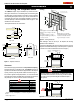
7”
1 3/4”
2 3/8”
1 3/4”
Figure 3. Backframe dimensions.
Backframe Min. 42”
both sides Typical
Com
b
usti
bl
e materia
l
s may
b
e use
d
,
(left & right), surround & bottom.
Above fireplace see Fig. 24 & 25.
Framing Kit, (Part No. L42FS01B,
4-pcs. Fasten to Combustible
framing with supplied hardware.