
Owner`s manual


Page 4
L42DF-ST See-thru Indoor Gas Fireplace
Part No. XG0812 - 081009
f i r e f e a t u r e
L42DF-ST
Top - top vent *
12"
Top - rear vent
21"
Back
2"
Floor
0"
Vent ring
1"
Mantle **
6"
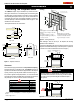
Installation
Installing The Fireplace Shell
The L42DF-STreplacemaybe installedinany locationthatmain-
tains proper clearances to air conditioning ducts, electrical wiring and
plumbing.Safety,aswellasefciencyofoperation,mustbeconsidered
whenselectingthereplacelocation.Trytoselectalocationthatdoes
notinterferewithroomtrafc,hasadequateventilation,andoffersan
accessible pathway for Direct Vent installation. Refer to page 4 - Vent
Installation for more information.
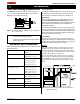
Thereplacedimensionsareshownbelow:
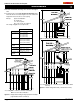
When installing a shelf over the top of the replace, the following
guidelines must be adhered to:
For Rear Vent applications the minimum clearance from the top of the
replacetocombustibleshelfframingis12"andforTopvent21".(Minimum
2" clearance must still be maintained around the vent pipes.)
Figure 2. Framing dimensions.
Framing
Top View
Front View
Side View
Clearances
These clearances apply to all dimensions except the framed opening,
where the clearance to combustibles is 0". The L42DF-ST clearance to
unprotectedcombustiblewallswhichareperpendiculartothereplace
opening, must not project beyond the shaded area shown in Fig. 24.
For protection against freezing temperatures, it is recommended that
outer walls of the chase be insulated with a vapor barrier. This will reduce
thepossibilityofacold-airconvectioncurrentonthereplace.
Figure 1. Fireplace dimensions.
* Clearance from top of the Fireplace to a combustible ceiling within the fireplace
enclosure.
** Refer to Pages, 10 & 11.
34 1/2”
5”
8”
23 7/8”
27 3/4”
Figure 2b. Framing dimensions. (Rear Vent)
4
1m in N.G.
21”
mi
n
PELS hort
90 elbow
shelf
supplied shield
RHS101
54 min L.P.
Figure 2a. Framing dimensions. (Top Vent)
WARNING!
When this appliance is installed directly on carpeting, tile or any
combustiblematerialotherthanwoodooring,itmustbeinstalled
on a metal or wood panel extending the full width and depth of
the appliance.
12
min.
shelf
supplied shield
90°
Notes:
Install supplied metal headers (Part No.
H42ST060) above fireplace after unit
is in place.
Use supplied hardware to attach to
framing. Both Walls Typical. May not
be exactly as shown.
5 1/2”
5 1/4”
18 1/2”
30 1/2”
39 1/2”
1 1/4”
1 1/4”
1 1/4”
1”
41 7/8”
41 7/8”
6 1/2”
23 7/8”
40 1/2”
8”
5”
Framing Kit, 4-pcs. (Part No.
L42FS01B) Install with supplied
hardware. Both walls and sides
Typical. See Figure 2a below.
40”
45”
23 3/4”
40”
36”
Both walls Typical. May
not be exactly as shown.