Installation & Maintenance Manual L42DF Indoor L-Series Residential Fireplace DANGER Read and understand this manual. Improper installation, adjustment, alteration, service or maintenance can cause serious injury, property damage or even death. For assistance or additional information consult a qualified installer, service agency or the gas supplier. CAUTION Glass doors on gas fireplaces are extremely hot while the fireplace is on and remain hot even after the fireplace has been turned off.
L42DF* Indoor Gas Fireplace NOTICE You must read and understand this manual prior to installation, operation or troubleshooting this appliance. Please retain this owner’s manual for future reference and maintenance. Table of Contents Safety Alert Key Introduction ..................................................................................3 Installation Before you Start ..................................................................................4 Installation Checklist....................
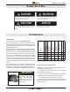
L42DF* Indoor Gas Fireplace Safety Alert Key DANGER WARNING Indicates a hazardous situation which, if not avoided, WILL result in death or serious injury or property damage. Indicates a hazardous situation which, if not avoided, COULD result in death or serious injury or property damage. CAUTION NOTICE Indicates a hazardous situation which, if not avoided, WILL result in minor or moderate injury.
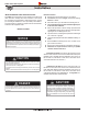
L42DF* Indoor Gas Fireplace Installation IMPORTANT MESSAGE: SAVE THESE INSTRUCTIONS The L42DF* Direct Vent fireplace must be installed in accordance with these Instructions. Carefully read all the Instructions in this manual first. Consult the Local Gas Branch to determine the need for a permit prior to starting the installation. It is the responsibility of the installer to ensure this fireplace is installed in compliance with the manufacturers instructions and all applicable codes.
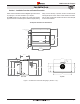
L42DF* Indoor Gas Fireplace Installation Section 1: Installation Overview and Product Dimensions Please review the Installation Checklist on Page 4 for general information on preparing for a successful installation of your fireplace. The L42DF* fireplace may be installed in any location that maintains proper clearances to air conditioning ducts, electrical wiring and plumbing. Safety, as well as efficiency of operation, should be considered when selecting the fireplace location.
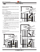
L42DF* Indoor Gas Fireplace Installation Section 2: Framing Frame in the enclosure for the unit with framing materials. The framed opening for the assembled fireplace is 42" wide, x 37" high x 22⅝" deep, see Figure 2. Combustible Header, with Supplied shield. 2” Min NOTE: When constructing the framed opening, please ensure there is access to install the gas line when the unit is installed. See Figure 23. 12” Max. N.G. Combustible Shelf REAR VENT N.G.
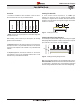
L42DF* Indoor Gas Fireplace Installation Clearances Installing The Standoffs Rear Sides Floor Mantel 10" Top - Top vent † L42DF* Top - Rear vent † MODEL 1” clearance is maintained on sides and bottom of vent runs and 2” above horizontal vent runs to any combustible material. 21" 2" 1" 0" 6" † NOTE: Clearance from top of fireplace to a combustible ceiling within the fireplace enclosure.
L42DF* Indoor Gas Fireplace Installation Framing the Heat Shield Included with the L42DF* Gas fireplace, is a framing heat shield Kit. This Kit is fabricated from galvanized steel and arrives with three (3) pieces, as shown below. The shields protect all adjacent combustible materials, mantels and mouldings from excessive heat radiated by the fireplace. NOTE: The shields must be installed as shown in Figures 9 - 9b. Step 3. Nail or screw the top shield in place flush with framing, as shown in figure 9b.
L42DF* Indoor Gas Fireplace Installation Section 3: Venting Montigo supplies a variety of direct venting and termination options. The direct vent termination location MUST be selected such that it is the highest point in the venting assembly. It should also be selected such that it provides the shortest vent run possible.
L42DF* Indoor Gas Fireplace Installation Section 3-2: INSTALLING A ROOF MOUNTED DIRECT VENT TERMINATION (PVTK-1) PVTK1 Termination 2’ min. This section applies to installations where the direct vent termination will be roof mounted. Section 3-2-1: VENTING LAYOUT Selection of components and details of venting lay out should adhere to the following guidelines: The maximum termination point is 32’ above the fireplace (NOTE: if the maximum termination height is used, the flame pattern may be affected).
L42DF* Indoor Gas Fireplace Installation PVTK1 Termination MEXT Sections Support plate 32’ max Support ring 12” Max. Figure 11c. Rear vent, Roof mounted venting (1 = 90° bend). XG0181 -112811.
L42DF* Indoor Gas Fireplace Installation Section 3-3: INSTALLING A WALL MOUNTED DIRECT VENT TERMINATION This section applies to installations where the direct vent termination will be wall mounted. Installation of termination from inside structure A Termination with a MOSR Frame is installed from the inside of the structure. These are commonly used in high-rise construction.
L42DF* Indoor Gas Fireplace Installation Section 3-3-1: VENTING LAYOUT: Wall mounted termination. Selection of components and details of venting layout should adhere to the following guidelines: Vent terminations must not be recessed in walls or siding. For Heat Shield requirements see Section 3-3-3. Once the proposed venting layout has been determined refer to Figure 14 or 16 to ensure the layout is acceptable.
L42DF* Indoor Gas Fireplace Installation 120” Max Heat Shield 96”Min. Figure 14c. Top Vented, wall mounted Retracted Multi-elbow installation. See Venting Graph for Top vent, wall mounted terminations, Figure 14. Page 14 XG0181 - 112811.
L42DF* Indoor Gas Fireplace Installation 45° Corner Installation. Attach an PEL-45 (45° elbow) directly onto the flue collar. Cut the PXT20 to suit, and attach it to the PEL-45. Slide the fireplace into position and attach to the termination. 45° or less Corner Installation. Use an PTO-4 termination and an PFL-1 or PFL-2/PFL-2 (12" or 24" compressed length) and a frame, if appropriate. Flex may be turned to obtain desired degree of angle required but must not exceed 45°.
L42DF* Indoor Gas Fireplace Installation Notes Wall Mounted Terminations: REAR VENT ■ All dimension lengths for vertical or horizontal runs are measured from center of the vent pipe. ■ Venting runs must fall within the limits set by the venting graphs, see Figure 16. ■ Fireplace must be converted to Rear Vent configuration prior to running vent, see Figure 10 and 10a.
L42DF* Indoor Gas Fireplace Installation Section 3-3-2: VENTING COMPONENTS The following components and associated Montigo part numbers for installation of a roof or wall mounted termination. Use only Montigo Vent Components. Use of non-Montigo parts will VOID the warranty and may impede operation of the fireplace.
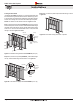
L42DF* Indoor Gas Fireplace Installation Section 3-3-3: Heat Shields Installing a Wall Mounted RHS8 Heat shield The RHS8 Heat shield CANNOT be used when the Termination is WITHIN (36" Min. horizontal and 46" Min. vertical) from the fireplace, or directly off the rear of the fireplace, as shown figure 17a. The RHS101 Heat Shield (Figure 18c and 18a) MUST be used within the noted dimensions. To install the RHS8, frame an opening in combustible construction, Figure 17 below.
L42DF* Indoor Gas Fireplace Installation Section 4: Wiring Models L42DFN-F ON / OFF (CPI / IPI MODE Not Used) ON/OFF Orange Green L42DFL-F IPI/CPI Battery Holder 4 x 1.5V AA Type Red Black 880 Valve VALVE BATTERY Chassis connection 120 Vac INPUT GROUND DFC 7 Vdc STABILIZED SUPPLY OUTPUT DC SUPPLY Figure 19.
L42DF* Indoor Gas Fireplace Installation Installing the remote On/Off Wall Switch Top / Rear Intake Air Adjustment Wiring for the optional Fan Kit Figure 22. Closed Vane for Top Vent Fireplaces. The L42DF* gas valve may be connected to a wall switch. Do NOT connect any external power to the remote switch. The valve will generate its own power on a millivolt circuit or will draw its power from an AC Connection inside the fireplace, depending on the model of the unit.
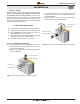
L42DF* Indoor Gas Fireplace Installation Section 5: Installing the Gas Line Section 5-1: FUEL CONVERSION ■ Verify that your fireplace is compatible with your available gas type. (Natural Gas or Propane shown by "N" or "L" in your model number ■ If gas type is not compatible, contact your local Montigo representative to purchase a conversion kit. ■ Conversion kits must be installed by a qualified service technician. 0.875 dia. 3 1/2 10 7 Figure 23. Gas line access.
L42DF* Indoor Gas Fireplace Installation Section 6: Finishing Finishing Around the Fireplace Combustible mantels and mouldings may be safely installed over the top and on the front of the fireplace provided that they do not project beyond shaded area shown in Figure 24.
L42DF* Indoor Gas Fireplace Installation Section 7: Installing & Removing the Door Removing the door: The L42DF* door is removed in a few simple steps. Follow these instructions below to remove the Horizontal access panel, unlatch the door buckles and, remove the door. Replace in reverse order. Step 1: Remove the Horizontal cover by placing fingers in both finger holes, then pushing away from you and lifting out. Place it aside during maintenance or cleaning. Install in reverse order.
L42DF* Indoor Gas Fireplace Installation Installing Firestones in Natural Gas and Propane Fireplaces The L42DF* fireplace is supplied with firestones. Remove the glass door. Follow these instructions to ensure all parts are removed or replaced as required. Once the glass door is removed place the firestones randomly across the pan as described in Figure 27 to 27a.
L42DF* Indoor Gas Fireplace Operation Section 9: Start-up Sequence Standing (Continuous) Pilot Ignition (SIT NOVA 820) For Your - READ BEFORE LIGHTING: withSafety American Flame Electronic Ignition WARNING If the information in these instructions is not followed exactly, a fire or explosion may result causing property damage, personal injury or death. A. This appliance has a pilot which must be lit by hand. When lighting the pilot, follow these instructions exactly. B.
L42DF* Indoor Gas Fireplace Operation SIT Proflame Electronic Ignition For Your Safety - READ BEFORE LIGHTING: with American Flame Electronic Ignition WARNING If the information in these instructions is not followed exactly, a fire or explosion may result causing property damage, personal injury or death. A. This appliance is equipped with an ignition system that lights the pilot burner automatically. Do not attempt to light the pilot by hand. B.
L42DF* Indoor Gas Fireplace Maintenance Lighting Instructions See pages 25 to 26. General Have the fireplace and installation inspected yearly. The inspection must include, but is not limited to, the following: • A visual check of the entire vent system and termination. • An inspection of the explosion relief flappers and the door gaskets to ensure a proper seal. • An inspection of the burner, vent run, and primary air openings. • An inspection of the gas valve, gas components, and pilot flame.
L42DF* Indoor Gas Fireplace Maintenance Troubleshooting SIT Nova 820: SIT Proflame System: The following is a troubleshooting chart of possible problems: The following is a troubleshooting chart of possible problems: PROBLEM SOLUTION PROBLEM SOLUTION Noisy Pilot Flame Locate pilot adjustment screw on gas control valve. Flame is decreased by turning adjustment screw clockwise. Pilot won't ignite or spark. Pilot won’t ignite Disconnect remote wires and try to light pilot.
L42DF* Indoor Gas Fireplace Replacement Parts Continuous Pilot SIT Nova 820 SIT Proflame N.G. - Gas Valve RGC1006 N.G. - Gas Valve RGC3044 L.P. - Gas Valve RGC1005 L.P. - Gas Valve RGC3045 N.G. - Pilot Assembly RPA020 N.G. - Gas Valve Stepper Motor RGC3033 L.P. - Pilot Assembly RPA021 L.P. - Gas Valve Stepper Motor RGC3034 ** N.G. - Pilot Assembly RPA033 N.G Burner Orifice R0R1120 L.P. - Pilot Assembly RPA034 L.
L42DF* Indoor Gas Fireplace Appendix Appendix A: Venting Terminations Location Canada* USA** A clearance to the termination frame above grade, veranda, porch, deck, or balcony 12 inches 12 inches B clearance to top of doors or operable windows 12 inches 12 inches C clearance to sides or bottom of door or operable windows 12 inches 9 inches D clearance to permanently closed window when installed with approved gas penetration termination 0 0 E clearance to permanently closed window Recom
L42DF* Indoor Gas Fireplace Appendix Appendix B: Warranty The Warranty The Companies warrants the Montigo Gas Appliance to be free from defects in materials and workmanship at the time of manufacture. On the Montigo fireplace, there is a ten-year warranty on the firebox and its components, a five-year warranty on the main burner and pilot burner, and a one-year warranty on the gas control valve, fibre logs and Power Vent Module.
L42DF* Indoor Gas Fireplace Appendix Appendix C: State of Massachusetts Amendment (Gas Fireplace / Equipment sold in the State of Massachusetts) 5.08: Modifications to NFPA-54, Chapter 10 (1) Revise NFPA-54 section 10.5.4.
L42DF* Indoor Gas Fireplace Notes XG0181 - 112811.
L42DF Residential Gas Fireplace Ferndale, Washington TF: 1.800.789.6236 FX: 1.866.3000.0927 XG0181 - 112811.1 Langley, British Columbia TF: 1.800.378.3115 FX: 1.604.607.