
Owner`s manual

XG0147 - 011912.1
Maintenance
See pages 26 to 28.
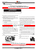
CAUTION!
Fireplace gas control must be in the “OFF” position and pilot
and main burners extinguished when cleaning appliance with
a vacuum.
Doors can get very hot. Handle only when cool.
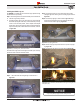
When the replace is rst activated, there may be some smoking and
a visible lm may be left on the glass. This is a normal condition, and is
the result of burning of protective coatings on new metal.
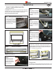
Glass must be cleaned periodically to remove any lm (which
is a normal by-product of combustion) which may be visible.
Film can easily be removed by removing the door, as shown on
. Handle the door carefully, and clean it with nonabrasive
glass cleaners. One of the most effective products is Kel Kem.
Silicone seals on inner door during initial ring will "off gas",
leaving a visual deposit of a white substance on combustion
chamber walls. This can easily be removed from the chamber
walls using normal household products.
Use a vacuum cleaner or whisk broom to keep the control
compartment, burner, and rebox free from dust and lint.
Logs may be cleaned periodically with a vacuum to remove soot
or other contaminates.
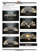
The is equipped with an adjustable burner, allowing you to
raise or lower the ames. To adjust the ames, locate the black knob
marked 'Hi-Lo', in the centre of the gas control valve (See Figure 30).
To raise the ame height, turn the black knob (located behind the
lower control compartment) .
To lower the ame height, turn .
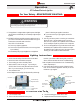
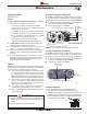
'Hi-Lo' Adjustment on the SIT Nova 820 gas valve,
The is equipped with an adjustable burner, allowing you to
raise or lower the ames. To adjust the ames, locate the black knob
marked 'Hi-Lo', in the centre of the gas control valve (See Figure 31).
To raise the ame height, turn the black knob (located behind the
lower control compartment) .
To lower the ame height, turn .
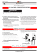
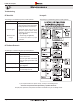
'Hi-Lo' Adjustment on the SIT Proame gas valve.
Manifold Pressure
Test Connection
Pilot Adjustment Screw
Hi Lo Adjustment
Inlet Pressure
Test Connection
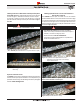
Locate Pilot Adjustment Screw. (See gure 30 or 31.)
Adjust pilot screw to provide properly sized ame as shown.
After installing or servicing, leak test with a soap solution with main
burner on. Coat pipe and tubing joints, gasket etc. with soap solution.
Bubbles indicate leaks. Tighten any areas where the bubbles appear
until the bubbling stops completely.
Manifold Pressure
Test Connection
Wall Switch
Power
Generator
Pilot Adjustment Screw
Inl
e
t Pr
essu
r
e
'Hi-Lo' Adjustment Knob
Gas Control Knob
(Shown in “Pilot” position)
For this appliance requires a minimum inlet pressure
of 5.5" W.C. and a manifold pressure of 3.5" W.C.
For this appliance requires a minimum inlet
pressure of 11" W.C. and a manifold pressure of 10" W.C.
Always keep the replace area clear and free of combustible
materials, as well as gasoline and other ammable vapours
and liquids.
Do not use this appliance if any part has been under water.
Immediately call a qualied service technician to inspect the
appliance and to replace any part of the control system and any
gas control which has been under water.
. The inspection
must include, but is not limited to, the following:
A visual check of the entire vent system and termination.
An inspection of the explosion relief appers and the door
gaskets to ensure a proper seal.
An inspection of the burner, vent run, and primary air openings.
An inspection of the gas valve, gas components, and pilot ame.
For your convenience a 1/8" manifold pressure tap is supplied
on the gas valve for a test gauge connection.
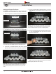
Ensure proper log placement as per this manual.
Inspection of all optional equipment; fans, thermostats, etc.