
Owner`s manual


XG0147 - 011912.1
Installation
The RHS8 Heat shield be used
of the replace, (see gure 15a). For applications within
these dimensions the RHS101 Heat Shield be used. .
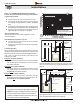
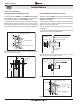
To install the RHS8, frame an opening in combustible construction,
Figure 15 below. Slide the Heat shield in place over the vent pipe
which attaches to the replace. After the replace and vent pipe has
been installed, clearances should match the dimensions in Figure 15.
RHS8 Installation. (Install by sliding over vent pipe where it passes
through the combustible construction).
RHS101 Installation. (Install by sliding Outer Section over vent pipe
where it passes through the combustible construction.
Heat Shield. After sliding the outer section in place.
RHS8 Installation. (Minimum requirements).
The RHS101 Heat shield be used where the RHS8 Termination
(Figure 15 and 15a) be used. Use the RHS101
or
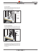
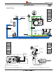
To install the RHS101, Slide the Inner Section over the vent pipe that will
connect to the replace. Fasten the vent pipe to the back of the replace
with a Min. of three sheet metal screws.
Next, slide the RHS101 outer section from the outside of the structure,
see Figure 16.
To complete the installation fasten the Heat Shield Outer Section &
Termination frame to the structure Figure 16a.
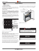
RHS8 Heat Shield
1” Min. Both sides Typical
1” Min.
1” Min.
Combustible Framing
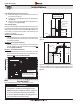
RHS101 Installation.
Outer Shield 10 1/4”
3/8” Min. Both sides Typical
3/8” Min.
3/8” Min
.
Combustible Framing
12” x 12”
Inner Shield 9 3/8”
Termination
Drywall / sheetrock
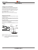
RHS101 Heat Shield, inner Section
RHS101 Heat Shield
Outer Section
Combustible
framing
Termination
Drywall / sheetrock
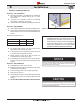
RHS101 Heat Shield, inner Section
RHS101 Heat Shield
Outer Section
Vent pipe, from fireplace
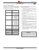
RHS8 Heat
Shield
36” Min
60” Min.