
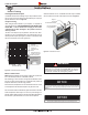
Owner`s manual


XG0147 - 011912.1
Installation
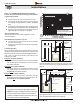
42”
46”
A
C
B
If your installation does not fall within
the venting graph para- meters,
please contact a local Montigo dealer
for Power Venting options.
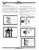
H*38DF* Top Vent Venting Graph for wall mounted terminations.
The Venting Graph
Measure the vertical height from the replace hearth to the centre of the
termination and the horizontal run from the replace ue collar to the wall
ange of the termination. Plot on the Venting Graph Figure 12 with an 'X'.
If the 'X' falls on or above the top boundary of the shaded area, the
installation is acceptable.
If the vertical dimension from the hearth is 114" and the horizontal
run to the wall ange of the vent termination is 168", this would be
an acceptable installation.
If the vertical dimension from the hearth is 48" and the horizontal
run to the wall ange of the vent termination is 72", this would be
acceptable installation.
If the vertical dimension from the oor of the replace is 60" and
the horizontal run to the wall ange of the vent termination is 144",
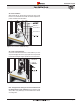
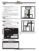
Vent terminations must not be recessed in walls or siding.
All through-the–wall terminations within 3’ of the replace must
have a Montigo Heat Shield (RHS101) installed. See
.
All through-the-wall terminations beyond 3' of the replace must
have a Montigo Heat Shield (RHS8) installed. See .
Once the proposed venting layout has been determined refer to
Figure 12 or 14 to ensure the layout is acceptable.
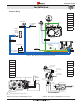
Top Vent
All measurements for vertical or horizontal runs are measured
from centre of the vent pipe.
Venting runs must fall within the limits set by the venting graph,
see Figure 12.
The following details are some possible congurations for Wall
mounted terminations.
Unacceptable vent run
within shaded area.
Acceptable vent run
within non-shaded area.
42"
Top Vented, wall mounted installation with one 90° bend. The vent
run must comply with Venting Graph for Top vent, wall mounted terminations,
Figure 12.
. Top Vented, wall mounted Multi-elbow installation. See Venting
Graph for Top vent, wall mounted terminations, Figure 12.
RHS8 Heat
Shield
Termination
Hearth
Exterior
Wall
42”Min. Rigid
46”Min. Flex
42” Max.
Flex section
shown
Solid Section
Flex Section
Hearth
30”min
15’foot Max.
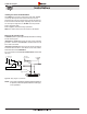
RHS8 Heat
Shield
Termination
Exterior
Wall
8' MIN
at MAX
horizontal
WARNING:
An inspection of the explosion relief appers and door
be made prior to lighting the replace. Faulty seal
on the door gasket and/or explosion ports will result in
products of combustion leaking into the living space and
may result in carbon monoxide poisoning.