
Owner`s manual


Page 9
HWDF-Series Gas Fireplace
Part No. XG0190 - 071409
PEL
Available Top Vent Components
The following venting components are available for the HW38-DF,
Top Vent:
4" / 7" Venting 5" / 8" Venting
A - Termination MTO-3(3"Length)
MTO-3F(3"Length)
PTO-3(3"Length)
PTO-3F(3"Length)
B - Stucco Kits MSR(StuccoFrame)
MOSR(StuccoCan)
BSR(BrickCan)
MSR(StuccoFrame)
MOSR(StuccoCan)
BSR(BrickCan)
C - Flex Sections MFL-1(12"Section)
MFL-2(24"Section)
MFL-3(36"Section)
MFL-4(48"Section)
PFL-1(12"Section)
PFL-2(24"Section)
PFL-3(36"Section)
PFL-4(48"Section)
D - Rigid
Sections
MEXT-1(12"m/fSection)
MEXT-2(24"m/fSection)
MEXT-3(36"m/fSection)
MEXT-4(48"m/fSection)
PEXT-1(12"m/fSection)
PEXT-2(24"m/fSection)
PEXT-3(36"m/fSection)
PEXT-4(48"m/fSection)
E - Elbows MEL-90MM(m/m90°Elbow)
MEL-90FF(f/f90°Elbow)
MEL-90FM(f/m90°Elbow)
PEL-90MM(m/m90°Elbow)
PEL-90FF(f/f90°Elbow)
PEL-90FM(f/m90°Elbow)
NOTES: All dimension lengths for vertical or horizontal runs are
measured from centre of the vent pipe.
Venting runs must fall within the limits set by the venting
graph(seeFigure7).
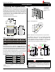
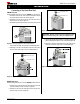
Example 1:
ForourshortestventingcongurationusecomponentsAandE(see
Figure 10).
Figure 10. Typical Top Vent installation. If the 90° elbow is installed
directly on the replace, for height to the center of the
termination see chart on page 3.
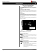
Important:
Aninspectionoftheexplosionreliefappersanddoormustbe
madepriortolightingthereplace.Thiswillensurethedoorgas-
keting material will provide an adequate seal during operation.
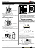
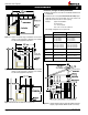
Horizontal Venting
Figure 11. Typical Top Vent installation. The solid sections can be used in
various combinations to obtain the desired vent run. The vent
run must fall within the limits set by the venting graph.
90° Elbow
MEXT Section
PEXT Section
Termination
Example 2:
Rigidsectionsandanelbowusedinconjunctionwith3ft.exsection
(MFL-3)will,whenextendedinavefootchase,allowforamaximum
horizontalrunoftwelveandone-halffeetfromthecentreofthereplace
tooutsidewallandaminimumof7'6"whenretractedinoppositedirection
(see Figure 12 and 13).
"C"exsectionsand"D"rigidsectionsmaybeusedinconjunctionwith
one another to obtain different possible horizontal length installations.
NOTE: Flex section with no vertical rise must not exceed maximum
horizontal length of 3 feet (see Figure 14). Flex runs over 3 feet must
fall within the limits set by the venting graph, and must have a minimum
verticalriseof3"perfootofex.
Installation