
Owner`s manual


Page 8
HW-Series Gas Fireplace
Part No. XG0190 - 071409
Installation
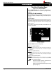
Example A: (Acceptable Installation)
If the vertical dimension from the hearth is 84" and the horizontal run to
the wall flange of the vent termination is 36", this would be an acceptable
installation.
Example B: (Acceptable Installation)
If the vertical dimension from the hearth is 90" and the horizontal run to
the wall flange of the vent termination is 126", this would be an acceptable
installation.
Example C: (Unacceptable Installation)
If the vertical dimension from the floor of the fireplace is 74" and the
horizontal run to the wall flange of the vent termination is 108", this would
NOT be an acceptable installation.
NOTES: All dimension lengths for vertical or horizontal runs are
measured from centre of the vent pipe.
Venting runs must fall within the limits set by the venting
graph(seeFigure7).
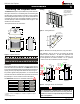
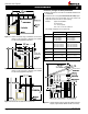
Figure 9b. HW38DF Top Vent Venting Graph
Top Vent Venting Runs
(may use 4"/7" Top Vent ONLY)
For the HW38DF Top Vent,thereare two types ofinstallations:A)
Through-The-Wall Installations and B) Vertical (Through-The-Roof)
Installations.
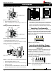
A) Through-The-Wall Installations
Before you install any venting, you must determine whether the venting
runwillbeacceptable.Unacceptableventingcanaffectthereplace's
combustion.
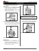
The Venting Graph
Measuretheverticalheightfromthereplacehearthtothecentreof
theterminationandthehorizontalrunfromthefromthereplaceue
collartothewallangeofthetermination.PlotontheVentingGraph
(Fig.9a)withan'X'.
Ifthe'X'fallsonorabovethetopboundaryoftheshadedarea,the
installation is acceptable.
B
C
A
36” LP
24” NG
42”
36
5/8 NG
60” NG
4/7 NG
5/8 LP
Power Vent models, LDVPV47
EDVRSPV58, and EDVWSPV58
to be used within the shaded area of
graph. (See Index of this guide for
applicable Product page).