
Owner`s manual


Page 6
HW-Series Gas Fireplace
Part No. XG0190 - 071409
Installation
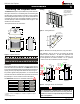
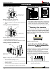
Installing Terminations with Built-In Frames
Installing Terminations with MSR Frames
1. Frametheterminationopeningto12"x12".
2. Fasten the termination to the studs using a minimum of 4 screws.
1. Frametheterminationopeningto11"x11".
2. Fasten the termination to the studs using a minimum of 4
screws.
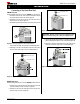
Installing Terminations with MOSR Frames
MOSR
1. Frametheterminationopeningto12"x12".
2. Fasten the MOSR frame to the interior side of the studs using a
minimum of 4 screws.
3. Insert the termination into the MOSR frame as shown here, and
attach by screwing through the four pilot holes in the termination.
MSR
MTO-3 (4"/7")
PTO-3 (5"/8")
MTO-3F (4"/7")
PTO-3F (5"/8")
MTO-3 (4"/7")
PTO-3 (5"/8")
MTKOG (4"/7")
PTKOG (5"/8")
1. Ensure that the two long mounting brackets are facing the bottom
ofthetermination.(Seeinset).Thiswillprovidemoreheatprotection
at the top of the termination, where temperatures are highest.
2. Attach to the faceplate of the termination using four sheet metal
screws.
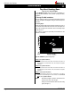
Installing Heat Guards over Terminations
Installing The Standoffs
To avoid elevated mantel temperatures, all HW38DF gas
replaces are required to have the supplied standoffs installed.
The replaceissupplied with two standoffs.Bend and install these
standoffsontopofthereplaceensuringthattheheightofthestandoff
maintainsa6.5"clearance.
Figure 6b. Installing the stando's.
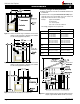
Installing the Nailing Flange
Extension, or Non-Combustible
material
The Nailing Flange Extension is supplied with all Montigo Flush face
gasreplaces.ThisExtensionisrequired,unlessNon-combustible
materialsareusedinitsplace,(seeFigure25).
Oncethereplaceismovedintotheframedopening,thesupplied
nailing extension, or Non-combustible material must be placed along
thetopedgeofthereplace.Thiscanbenailedorscrewedinplace
to the framing, as illustrated below.
Figure 5a. Installing a MTO / PTO termination.
Figure 5b. Installing a MTO / PTO termination with the MSR frame.
Figure 5c. Installing a MTO / PTO termination with the MOSR frame.
1212
12
Figure 5d. Installing a PTO termination heat guard.
11
11
12
1
2
Figure 6c. Installing the Nailing Flange Extension, or Non-combusti-
ble materials above replace.