
Owner`s manual


Page 12
HW-Series Gas Fireplace
Part No. XG0190 - 071409
Installation
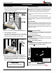
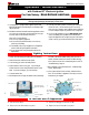
Figure 21a. Corner installation. (Installation Not Available for L.P.)
Figure 21b. Flex installation. (Installation Not Available for L.P.)
Note: Through the wall venting kits are also available for both
the Straight and the Corner Installation. The Kit includes a
heatsheild,anPFL-20(f/f)exiblepipe,andaterminationwithor
without a mounting frame.
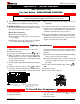
2. 45° Corner Installation.
AttachanPEL-45(45°elbow)directlyontotheuecollar.Cutthe
PXT-20tosuit,andattachittothePEL-45.Slidethereplaceinto
position and attach to the termination.
3. Corner Installation — 45° or less.
UseanPTO-3terminationandanPFL-2(12"or24"compressed
length)andaframe,ifappropriate. Flex may be turned to obtain
desired degree of angle required but must not exceed 45°.
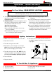
Important:
For Rear Vent units use 5/8 Vent ONLY
B. Multi-Elbow Installations
Formoredifcultinstallationsituations,theHW38-DFRearVentmaybe
installedwithtwo-90°elbowsandupto15'ofhorizontalrun.Ifusing
this installation option, you must adhere to the following guidelines:
therst90°elbowmustbeplaceddirectlyontheuecollar
youmusthaveaminimumverticalliftof50"(measuredfromthe
hearth)
your vent run must fall within the limits set by Figure 22b.
Before you install any venting, you must determine whether the venting
runwillbeacceptable.Unacceptableventingcanaffectthereplace's
combustion.
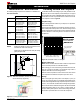
The Venting Graph
Measuretheverticalheightfromthereplacehearthtothecentreofthe
terminationandthehorizontalrunfromthereplaceuecollartothewall
angeofthetermination.PlotontheVentingGraph(Fig.22b)withan'X'.
Ifthe'X'fallsonorabovethetopboundaryoftheshadedarea,the
installation is acceptable.
Example A: (Acceptable Installation)
Iftheverticaldimensionfromthehearthis84"andthehorizontal
runtothewallangeoftheventterminationis36",thiswouldbe
an acceptable installation.
Example B: (Acceptable Installation)
Iftheverticaldimensionfromthehearthis90"andthehorizontal
runtothewallangeoftheventterminationis126",thiswouldbe
an acceptable installation.
Example C: (Unacceptable Installation)
Iftheverticaldimensionfromtheoorofthereplaceis78"and
thehorizontalruntothewallangeoftheventterminationis108",
this would NOT be an acceptable installation.
Figure 22b. HW38D-F Multi-Elbow Venting Graph.
PEL-45 Elbow
PXT-12
28 3/4”
A
C
B
18
”
5/8”NG & LP
Power Vent models, EDVPV47
LDVPV47, EDVRSPV47, and
EDVWSPV47 to be used within the
shaded area of graph. (See BELOW for
applicableProductinformation).