
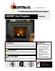
Owner`s manual


Page 10
HW-Series Gas Fireplace
Part No. XG0190 - 071409
Installation
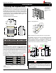
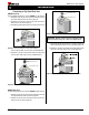
Figure 12. Extended Installation using a combination of solid and ex
venting. Use the vent graph to determine your allowable
run, then select appropriate components.
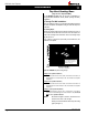
Figure 13. Retracted Installation using a combination of solid and ex
venting. Use the vent graph to determine your allowable
run, then select appropriate components.
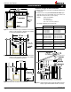
Figure 14. Horizontal ex installation with no vertical rise.
B. Vertical (Through-The-Roof) Installations
Minimumclearances2"fromventtoallcombustiblematerialsmust
be maintained.
A maximum of two offsets (each offset has two 90° bends) may be
made and shall not exceed total length of 25% of the vertical vent
height, when measured center to center of piping.
Example: Typical vent installation.
20' vertical vent
2 - 2' offsets required
25% of 20' = 5' max. offset allowed
This venting configuration meets requirements.
4" / 7" Venting 5" / 8" Venting
A - Termination MVTK-1 PVTK-1
B - Flex Sections MFL-1(12"Section)
MFL-2(24"Section)
MFL-3(36"Section)
MFL-4(48"Section)
PFL-1(12"Section)
PFL-2(24"Section)
PFL-3(36"Section)
PFL-4(48"Section)
C - Rigid Sections MEXT-1(12"m/fSection)
MEXT-2(24"m/fSection)
MEXT-3(36"m/fSection)
MEXT-4(48"m/fSection)
PEXT-1(12"m/fSection)
PEXT-2(24"m/fSection)
PEXT-3(36"m/fSection)
PEXT-4(48"m/fSection)
D - Support Ring
&Plate
MSPXT-8 PSPXT-8
E - Firestop FS-8 PS-8
F - Roof Flashing MRF-7(1/12-7/12pt.)
MRF-12(7/12-12/12pt.)
PRF-7(1/12-7/12pt.)
PRF-7(7/12-12/12pt.)
G - Adaptor / Vent
Reducer
PVA5487(5"/8"to4"/7")
Figure 15. Straight, vertical venting showing required MXT-10/PXT-10
adaptor (supplied with the MVKT-1/PVTK-1 termination).
MEXT/PEXT
MEXT/PEXT
MXT-10/PXT-10
45”
Min.
2’ max. 4”/7”
6’ max. 5”/8”