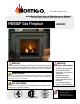
www.montigo.com Installation Operation & Maintenance Manual Check local codes and read all instructions prior to installation. HW38DF Gas Fireplace HW38DF HW38DF Shown Warning: Improper installation, adjustment, alteration, service or maintenance can cause injury or property damage. Refer to this manual. For assistance or additional information consult a qualified installer, service agency or the gas supplier.
HW-Series Gas Fireplace Warning: Read this manual before installing, operating or troubleshooting this appliance. Please retain this owner's manual for future reference. Congratulations Congratulations on selecting a Montigo gas fireplace, an elagent and well designed gas fireplace built to your specifications. The Montigo gas fireplace you have selected is designed to provide the utmost in safety, reliability, and engineering standards.
HWDF-Series Gas Fireplace Introduction Thank You for choosing a Montigo Gas Fireplace. About this Fireplace: The HW38DF is an Premium fireplace with a Designer LogSet. This fireplaces can be converted to both a Top Vent or Rear Vent application, (see specifics in the venting section of this instruction Manual), and are available in the specific models below. The HW38DF is rated for Natural Gas at 34,000 Max. BTU/H (9.96) Kilowatts Input and 30,000BTU/H for Liquid Propane.
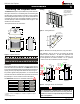
HW-Series Gas Fireplace Installation Installing The Fireplace Shell Framing * When sheetrock is not used behind the fireplace, framing depth may be reduced by 5/8" 37 3 /4” The HWDF-Series fireplace may be installed in any location that maintains proper clearances to air conditioning ducts, electrical wiring and plumbing. Safety, as well as efficiency of operation, must be considered when selecting the fireplace location.
HWDF-Series Gas Fireplace Installation Installing The Gas Line Vent Installation The gas line must be installed before finishing the HW38DF Fireplace. Natural Gas requires a minimum inlet gas supply pressure of 5.5" W.C. & a manifold pressure of 3.5" W.C. Propane Gas requires a minimum inlet gas supply pressure of 11" W.C. & a manifold pressure of 10" W.C. Provision must also be made for a 1/8" N.P.T.
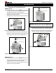
HW-Series Gas Fireplace Installation Installing Terminations with Built-In Frames Installing Heat Guards over Terminations 11 MTO-3F (4"/7") PTO-3F (5"/8") 11 MTKOG (4"/7") PTKOG (5"/8") Figure 5a. Installing a MTO / PTO termination. Figure 5d. Installing a PTO termination heat guard. 1. Frame the termination opening to 11" x 11". 2. Fasten the termination to the studs using a minimum of 4 screws.
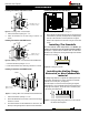
HWDF-Series Gas Fireplace Installation Converting to Top Vent/ Rear Vent 8” Outer Flue Cap HW38DF Top Vent Use the following instructions to convert a HW38DF, for Top Vent use: 1. Install the 5" inner flue cap on the rear flue outlet and secure the cap in place with five screws, as shown in figure 7a. 2. Install the 8" outer flue cap on the rear flue outlet, and secure it with five screws, as shown in figure 7a. 3.
HW-Series Gas Fireplace Installation Top Vent Venting Runs (may use 4"/7" Top Vent ONLY) For the HW38DF Top Vent, there are two types of installations: A) Through-The-Wall Installations and B) Vertical (Through-The-Roof) Installations. A) Through-The-Wall Installations Before you install any venting, you must determine whether the venting run will be acceptable. Unacceptable venting can affect the fireplace's combustion.
HWDF-Series Gas Fireplace Installation Available Top Vent Components The following venting components are available for the HW38-DF, Top Vent: 4" / 7" Venting 5" / 8" Venting A - Termination MTO-3 (3" Length) MTO-3F (3" Length) PTO-3 (3" Length) PTO-3F (3" Length) B - Stucco Kits MSR (Stucco Frame) MOSR (Stucco Can) BSR ( Brick Can) MSR (Stucco Frame) MOSR (Stucco Can) BSR ( Brick Can) C - Flex Sections MFL-1 (12" Section) MFL-2 (24" Section) MFL-3 (36" Section) MFL-4 (48" Section) PFL-1 (12" Se
HW-Series Gas Fireplace Installation B. Vertical (Through-The-Roof) Installations Minimum clearances 2" from vent to all combustible materials must be maintained. A maximum of two offsets (each offset has two 90° bends) may be made and shall not exceed total length of 25% of the vertical vent height, when measured center to center of piping. Example: Typical vent installation. 20' vertical vent 2 - 2' offsets required 25% of 20' = 5' max.
HWDF-Series Gas Fireplace Installation Rear Vent Venting Runs The HW38-DF Rear Vent has three possible installations which do not require vertical lift, all of these installations require that you install the RHS101 heat shield. Heat Shield The heat shield (RHS101) must be used on all installations straight through the wall, at the point where the vent pipe connects to the termination. With the heat shield, proper vent clearances can be maintained. The heat shield is not included with the fireplace.
HW-Series Gas Fireplace Installation B. Multi-Elbow Installations 2. 45° Corner Installation. Attach an PEL-45 (45° elbow) directly onto the flue collar. Cut the PXT-20 to suit, and attach it to the PEL-45. Slide the fireplace into position and attach to the termination. For more difficult installation situations, the HW38-DF Rear Vent may be installed with two - 90° elbows and up to 15' of horizontal run.
HWDF-Series Gas Fireplace Installation Installation Of Rear Vent DV Finishing Around the Fireplace The following venting components are available for an HW38-DF in a Rear Vent installation: Combustible mantels and mouldings may be safely installed over the top and on the front of the fireplace provided that they do not project beyond shaded area shown in Figure 24. Side wall clearances are 3". Combustible surrounds may be installed with 3" clearance to the side of the fireplace as shown in Figure 25.
HW-Series Gas Fireplace Installation Wiring Mantels & Surrounds NOTE: National Canadian Gas Association mantel test requirements are for fire hazard prevention to combustible materials. New technology, to meet consumer and government demands for the wise use of energy, has prompted us to manufacture many models of fireplaces which are hot, fuel and energy efficient.
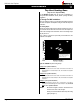
HWDF-Series Gas Fireplace Installation Removing and Installing the Door Removing the door: The H3W8DF Series door is removed in a few simple steps. Follow these Steps below to remove the Horizontal access panel, unlatch the door buckles and, remove the door. Replace in reverse order. Step 1: Remove the Horizontal Access Panel: Remove the Horizontal cover by placing fingers in both finger holes, then pushng away from you and lifting out. Place it Finger Holes aside during maintenance or cleaning.
HW-Series Gas Fireplace Installation Installing the Log Set Installing the LogLogs: 'D' 3. Place the top right log as shown below in figure 29d. Align the tab on the underside of the log, far right end, with the provided notch in the bottom right log, Figure 29c. The HW38-DF is supplied with five ceramic fibre logs. Unpack the logs and handle them very carefully. Notch Back Left Log Mounting Tray Bottom Left Log Mounting Tray Bottom Right Log Mounting Tray Figure 29a.
HWDF-Series Gas Fireplace Operation - Model HW38DF with Continuous Pilot For Your Safety - READ BEFORE LIGHTING: WARNING: If you do not follow these instructions exactly, a fire or explosion may result causing property damage, personal injury or loss of life. A. This appliance has a pilot which must be lighted by hand. When lighting the pilot, follow these instructions exactly. ■ If you cannot reach your gas supplier, call the Fire Department. B.
HW-Series Gas Fireplace Operation - Model HW38DF-I with Honeywell Electronic Ignition For Your Safety - READ BEFORE LIGHTING: WARNING: If you do not follow these instructions exactly, a fire or explosion may result causing property damage, personal injury or loss of life. A. This appliance is equipped with an ignition system that lights the pilot burner automatically. Do not attempt to light the pilot by hand. B. BEFORE LIGHTING smell all around the appliance area for gas.
HWDF-Series Gas Fireplace Operation Operation -- Model Model HW38-DF-F HW38DF-F with Proflame SIT Electronic Ignition with American For Your Safety - Flame READElectronic BEFORE Ignition LIGHTING: WARNING: If you do not follow these instructions exactly, a fire or explosion may result causing property damage, personal injury or loss of life. A. This appliance is equipped with an ignition system that lights the pilot burner automatically. Do not attempt to light the pilot by hand. B.
HW-Series Gas Fireplace Operation Maintenance Lighting Instructions General ■ Have the fireplace and installation inspected yearly. The inspection must include, but is not limited to, the following: See pages 15 and 19. Burner Adjustment The HW38DF is equipped with an adjustable burner, allowing you to raise or lower the flames. To adjust the flames, locate the black knob marked 'Hi-Lo', in the centre of the gas control valve (See Figure 32). The front burners are not adjustable.
HWDF-Series Gas Fireplace Maintenance Gas Control Valve Troubleshooting Power Generator HONEYWELL SV9500 /9600 Troublshooting Sequence Pilot Adjustment Screw Wall Switch NOTE: Before Troubleshooting, Familiarize Yourself With START The Startup And Checkout Procedure. Manifold Pressure Test Connection Spill Switch SV9500 / SV9600 is powered (24VAC nominal) NO Figure 33. Sit Nova 820 gas valve. Pilot Burner Adjustment YES 1. Locate Pilot Adjustment Screw. (See figure 34.) 2.
HW-Series Gas Fireplace Maintenance HW38-DF-F Troubleshooting Follow this information to reset the SIT System: 1. Locate the lead to the battery backup, (remove) (Refer to schematic, below) 2.
HWDF-Series Gas Fireplace Warranty The Warranty The Companies warrants the Montigo Gas Appliance to be free from defects in materials and workmanship at the time of manufacture. On the Montigo, there is a ten-year warranty on the firebox and its components, a five-year warranty on the main burner and pilot burner, and a one-year warranty on the gas control valve and fibre logs. Glass, plated/painted finishes, and refractory lining are exempt.
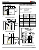
HW-Series Gas Fireplace Appendix A - Termination Locations A = clearance to the termination frame above grade, veranda, porch, deck, or balcony [16 inches (41 cm) minimum] N= B = clearance to door, or sides and top of window, that may be opened [16 inches (41 cm) minimum for appliances ≤100 000 BTU/H (30kW)] P = clearance under veranda, porch, deck, or balcony [16 inches (41 cm) minimum‡ to non-combustibles] [22 inches (56 cm) minimum‡ to combustibles] clearance above paved sidewalk or a paved drivewa
HWDF-Series Gas Fireplace Appendix B - State of Massachusetts Amendment (Gas Fireplace / Equipment sold in the State of Massachusetts) 5.08: Modifications to NFPA-54, Chapter 10 (1) Revise NFPA-54 section 10.5.4.
HW-Series Gas Fireplace Notes Page 26 Part No.
HWDF-Series Gas Fireplace Notes Part No.
XG0190 - 061509 Canadian Heating Products Inc. Montigo Del Ray Corp.