
Owner`s manual


Page 11
H(L)38DF-PRC Indoor Panorama Gas Fireplace
Part No. XG0211 - 080510
Installation
Section 3-3-1: VENTING LAYOUT
Selection of components and details of venting layout should
adhere to the following guidelines:
Vent terminations must not be recessed in walls or siding.
All through-the–wall terminations within 3’ of the replace must
have a Montigo Heat Shield (RHS101) installed. See Section
3-3-3.
All through-the-wall terminations beyond 3' of the replace must
have a Montigo Heat Shield (RHS8) installed. See Section 3-3-3.
Once the proposed venting layout has been determined refer to
either Figure 15 or Figure 16 to ensure the layout is acceptable.
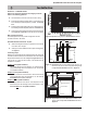
Notes Wall Mounted Terminations: Top Vent
All dimension lengths for vertical or horizontal runs are measured
from center of the vent pipe.
Venting runs must fall within the limits set by the venting graphs,
see Figure 15.
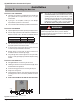
The Venting Graph
Measure the vertical height from the replace hearth to the centre of the
termination and the horizontal run from the replace ue collar to the wall
ange of the termination. Plot on the Venting Graph Figure 15 with an 'X'.
If the 'X' falls on or above the top boundary of the shaded area, the
installation is acceptable.
Example A: (Acceptable Installation)
If the vertical dimension from the hearth is 114" and the horizontal
run to the wall ange of the vent termination is 168", this would be
an acceptable installation.
Example B: (Uncceptable Installation)
If the vertical dimension from the hearth is 48" and the horizontal
run to the wall ange of the vent termination is 72", this would be
would NOT be an acceptable installation.
Example C: (Unacceptable Installation)
If the vertical dimension from the oor of the replace is 60" and
the horizontal run to the wall ange of the vent termination is 144",
this would NOT be an acceptable installation.
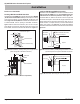
Wall mounted Terminations
The following details are some possible congurations for Wall
mounted terminations. See below.
42”
46”
A
C
B
If your installation does not fall
within the venting graph para-
meters, please contact Montigo
for Power Venting options.
Figure 15. Top Vent Venting Graph for wall mounted terminations.
Figure 15a. Top Vented, wall mounted installation with1 elbow (1 one
90° bend). The vent run must comply with Venting Graph
for Top vent, wall mounted terminations, Figure 15.
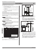
Figure 15b. Top Vented, wall mounted Multi-elbow installation. See
Venting Graph for Top vent, wall mounted terminations,
Figure 15.
Solid Section
Flex Section
Hearth
30”min
150”max
RHS8 Heat
Shield
Termination
Exterior
Wall
RHS8 Heat
Shield
Termination
Hearth
Exterior
Wall
46”
Min.
42” Max.
Flex section