
Installation Sheet


2
6/2021
© 2021 Monte Carlo Fan Collections
Warning: Before you begin installing the fan, Switch power off at Service panel and lock service disconnecting means to prevent
power from being switched on accidentally. When the service disconnecting means cannot be locked, securely fasten a warning
device, such as a tag, to the service panel.
Use AC 120V/60HZ power supply only.
Black
Black
Black
White
White
White
Blue
Green/Ground
Power
source
Wall switch
Receiver
Receiver
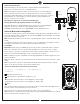
Make wiring connections using wire connectors provided as
the illustration shown in the Fig.2. White from fan to White
from remote marked to motor N. Black from fan to Black
from remote marked to motor L. Blue from fan to Blue from
remote marked FOR LIGHT. White (Neutral) from house to
White from remote marked AC IN N. Black (Live) from house
to Black from remote marked AC IN L. Connect all green
grounded wires to Grounded wire from House. Make sure that
no filaments are outside of the wire connectors.
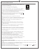
Insert the remote receiver into mounting bracket.
After making the wire connections, the wires should be
spread apart with the grounded conductor and the
equipment-grounding conductor on one side of the outlet box
and ungrounded conductor on the other side of the outlet
box. The splices after being made should be turned upward
and pushed carefully up into the outlet box.
Place the wi-fi antenna outside canopy and stick/fix it onto
ceiling. (Fig.3)
Caution: The installation has to be complete before operate
the fan.
Refer to the fan installation instruction manual
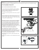
For fans that have been installed with a remote controller,
remove the canopy and disconnect lead wires. Remove the
receiver and replace it with the new receiver. (Fig.1,2)
Make wiring as shown in the Fig.2
For new fans, make wiring with the new receiver as shown in
the Fig.2.
For fans with pull chain controller, make sure the fan is set at
HIGH speed and the light is in the ON position by pull chain
controls originally supplied with your fan. Make wiring with the
new receiver as shown in the Fig.2
Wi-Fi antenna
Canopy
Fig.1
Fig.2
Fig.3
Canopy
Receiver