
Instructions / Assembly


© 2013 Monte Carlo Fan Company
6/25/2013
5
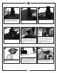
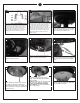
Attach glass by locating dimples in
light kit with the groves in glass and
twist clockwise till tight.
27
Attach blades to motor using screws
and washers in hardware bag and
tighten screws securely.
22
Connect white wire from fan to white
wire from light fixture. Then plug blue
wire from fan to red wire form light
fixture.
24
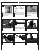
Remove 1 screw and loosen the
other 2 screws. Save screw.
23
Make wire connections to power source using
wire nuts provided. Make sure that no filiments
are outside of the wirenut. After making the
wire connections, the wires should be spread
apart with the grounded conductor and the
equipment-grounding conductor on one side of
the outlet box and ungrounded conductor on
the other side of the outlet box. Splices after
being made should be turned upward and
pushed carefully.
20
Make wiring connections as indicated above.
White from fan to white from remote marked
N. Blue from fan to blue from remote marked
light. Black from fan to Black from remote
marked L. White from house to white from re-
mote marked AC N . Black from house to
Black from remote marked AC L. Connect all
green ground wires to Ground wire from
House.
19
white
black
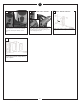
Lift canopy and install knurled nuts as
shown. Tighten the knurled nuts securely.
The canopy should adjust for any irregu-
larity in the ceiling or Outlet box.
21
Attach light fixture onto the plate on
motor assembly, aligning its keyhole
slots with the screws on plate and
twist clockwise till lock. Re-install the
screw removed in step 23. Tighten all
screw securely.
Install 2 x 10-watt medium base
dimmable, enclosed type of LED
lamps. California Title 24 compliant
bulbs included
Caution: Approved for use with LED
light bulb only (Part No. 97502S).
Do not use incandescent light
bulb. Caution: Do not replace bulb
until it cools down.
26
25