Owner’s Guide and Installation Manual 5SBR56XXD-L Series Fan UL Model No. : AC-556LF4000 Attach sales receipt to this card and retain as your proof of purchase DATE OF PURCHASE: RETAILER NAME: MODEL NUMBER: RETAILER ADDRESS: To register your fixture, please visit our website www.montecarlofans.com 18.5 kgs 40.
WARNING: TO REDUCE THE RISK OF FIRE, ELECTRIC SHOCK, OR INJURY TO PERSONS, OBSERVE THE FOLLOWING READ AND SAVE THESE INSTRUCTIONS Installation work and electrical wiring must be done by qualified person(s) in accordance with applicable codes and standards (ANSI/NFPA 70-1999), including fire-rated construction. Use this unit only in the manner intended by the manufacturer. If you have any questions contact the manufacturer.
1 2 Before you begin installing the fan, Switch power off at Service panel and lock service disconnecting means to prevent power from being switched on accidentally. When the service disconnecting means cannot be locked, securely fasten a prominent warning device, such as a tag, to the service panel. Warning-Risk of fire, electric shock, or personal injury.
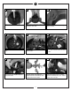
10 11 12 Remove 3 screws on arch hub. Use 3 screws removed to attach arch brackets to arch hub. Use 3 thumb screws to attach upper glass to holder. 13 14 15 Install upper glass and holder to fan body. Install 4 x 25 watt incandescent candelabra bulbs. Loosen lock nuts and screws on yoke till you can not feel screws on inside of yoke. 16 17 18 Remove keeper from cross pin and then cross pin from yoke. Replace keeper on cross pin and save.
19 20 21 Safety cable installation Safety Cable Lag Screw safety cable washer 3” lag screw lock washer Tighten 2 downrod set screws and lock nuts. Hang assembled fan from the mounting bracket installed to ceiling in previous step. Make sure the fan is hanging straight. Rotate fan until the tab on the Mounting bracket engages the slot on the Downrod Ball. This must be done to prevent the fan body from rotating when the blades are in motion.
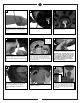
28 29 30 Place blade arms onto the other side of the blade and aligning holes. Insert screws with fabric washers though the holes and tighten securely. Install all 5 fan blade assemblies to the motor as shown above. Tighten screws securely. Loosen 2 of the 3 screws that will hold the light kit. Remove the screw that is associated to the closed hole on the light kit. 31 32 33 Plug white wire from fan to white wire from light kit. Then plug black wire from fan to black wire from light kit.
37 HAND HELD INSTALL Place face plate over battery compartment and buttons. Place remote over 2 pins on front cover. Attach cover of remote by placing over 4 pins and snaping into place. © 2011 Monte Carlo Fan Company 38 WALL MOUNT INSTALL Install wall control unit to outlet box using machine screws provided. 7 39 Attach front cover to wall control with screws provided. Snap battery cover in place.
Remote Control Transmitter Features: LED LIGHT FAN REVERSE (Press once to change direction of the fan)Fan must be running to reverse. MEDIUM SPEED HIGH SPEED LOW SPEED UPLIGHT ON/OFF SETTING AND DIMMER (Press and hold to dim light infinitely) FAN OFF SETTING (Turns fan off only) DOWNLIGHT ON/OFF SETTING AND DIMMER (Press and hold to dim light infinitely) FAN SPEED Depress “1 dot” for low speed, “2 dots” for medium or “3 dots” for high. To turn fan off press square”.
Trouble Shooting If you have difficulty operating your new ceiling fan, it may be the result of incorrect assembly, installation, or wiring. In some cases, these installation errors may be mistaken for defects. If you experience any faults, please check this Trouble Shooting Chart. If a problem cannot be remedied, or you are experiencing difficulty in installation, please call our Customer Service Center at the number printed on your parts list insert sheet.
Jul.2013 for CUL regulation REV.