
Installation Guide
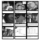


Install all 5 fan blade assemblies to the motor
as shown above. Tighten screws securely.
Loosen 2 of the 3 screws that will hold the light
kit. Remove the screw that is associated to the
closed hole on the light kit.
29
30
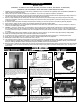
Make wire connections to power source using
w
ire nuts provided. Make
sure that no filiments
are outside of the wirenut. After making the
wire connections, the wires should be spread
apart with the grounded conductor and the
equipment-grounding conductor on one side of
the outlet box and ungrounded conductor on
the other side of the outlet box.
24
Lift Canopy to ceiling aligning the key hole slots
with the screws on the bottom of the Mounting
bracket. Rotate the canopy Counter Clockwise
to lock in place. Tighten the screws to secure
the Canopy. See inset for Keyhole shape
27
H
ang assembled fan from the mounting bracket
i
nstalled to ceiling in previous step. Make sure
the fan is hanging straight. Rotate fan until the
t
ab on the Mounting bracket engages the slot
o
n the Downrod Ball. This must be done to
prevent the fan body from rotating when the
b
lades are in motion.
20
Re-install safety bar removed in step. 3 by
placing safety bar on screws, sliding into place,
and tightening the 2 screws.
25
Tighten 2 downrod set screws and
lock nuts.
19
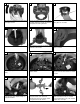
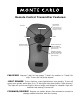
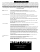
Set dip switches on the Remote T
r
ansmitter and Remote
Receiver to the same settings. This must be done so the
units will communcate properly. If you have other fans you
can set to control from one tr
ansmitter by setting both
receivers the same as the transmitter. If you have more
than one fan with remote. You can set the dip switches to
different positiosns to have seperate control.
Remote Transmitter Dip swtiches
Remote Receiver Dip switches
26
Place blade arms onto the other side of the
blade and aligning holes. Insert screws with
fabric w
ashers though the holes and tighten
securely.
28
Fan and light kit combinations over 35 lbs,
in both flush and downrod mode the safety
c
able must be installed into the house struc-
ture beams using the 3” lag screws,washers,
and lock washers. provided. Make sure that
when the safety cable is fully extended the
lead wires are longer than the cable and no
stress is placed on the lead wires.
21
Safety cable installation
S
afety Cable
Lag Screw
safety
cable
3
” lag
screw
l
ock
washer
w
asher
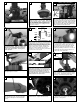
Install remote receiver by sliding into opening in
the Mounting bracket. Make sure that the dip
switches on the Transmitter and the Receiver
are set to the same position. See Fig 39 for
remote operation
22
w
hite
black
Make wiring connections as indicated above.
White from fan to white from remote marked
N. Orange from fan to Orange from remote
mark
ed Light/up
. Blue from fan to blue from
remote mark
ed down light. Black from fan to
Black from remote mark
ed L. White from
house to white from remote marked AC N .
Black from house to Black from remote
marked AC L. Connect all green ground wires
to Ground wire from House.
o
range
b
lue
Green
w
hite
b
lack
House
Fan
23