
Instructions / Assembly

6
© 2014 Monte Carlo Fan Company
12/2017
17 18
19
20
21
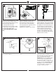
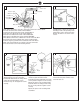
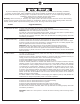
Make wiring connections using wire connectors provided as indicated above.
Red from fan to Red from remote marked Motor 1.
Purple from fan to Purple from remote marked Motor 2.
Gray from fan to Gray from remote marked Motor 3.
Blue from fan to Blue from remote marked FOR LIGHT.
White from fan to White from remote marked FOR LIGHT.
White (Neutral) from house to White from remote marked AC IN N.
Black (Live) from house to Black from remote marked AC IN L.
Connect all green grounded wires to Grounded wire from House.
Make sure that no filaments are outside of the wire connectors.
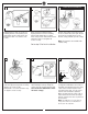
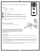
Insert the remote receiver into mounting bracket.
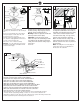
Partially loosen 2 of the set screws on
mounting bracket corresponding to the
slotted holes on the canopy upper ring.
Remove the other 2 set screws. Save
screws.
Raise canopy to mounting bracket,
aligning loosened screws in mounting
bracket with slotted holes in canopy. Twist
canopy to lock. Reinstall the screws
removed in step 18 and tighten all screws
securely.
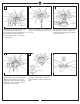
Align the holes of blade bracket, blade
and the top plate of blade bracket.
Install blade bracket with blade by 4 blade
screws provided. Tighten screws securely.
Repeat this process for remaining blades.
Install the blade assembly to motor using
the set screws provided. Tighten screws
securely
Repeat this process for remaining blade
assemblies.
Loosen 2 and remove 1 preassembled set
screws from the plate on motor. Save
screw for later use.
Blade
Blade assembly
Top plate
Blue (For Light)
White (For Light)
Red (Motor 1)
Purple (Motor 2)
Gray (Motor 3)
Black (AC IN L)
White (AC IN N)
Green/Ground
Wall Switch
Black (Live)
White (Neutral)
Power source
Blade bracket
Receiver