Owner’s Guide and Installation Manual 5DIC44XXXD-V1 Series Fan CUL Model NO. : 5DIC44XXXD-V1 Attach sales receipt to this card and retain as your proof of purchase DATE OF PURCHASE: RETAILER NAME: MODEL NUMBER: RETAILER ADDRESS: To register your fixture, please visit our website www.montecarlofans.com 7.9 kgs 17.
Cautions and Warnings WARNING: TO REDUCE THE RISK OF FIRE, ELECTRIC SHOCK, OR INJURY TO PERSONS, OBSERVE THE FOLLOWING READ AND SAVE THESE INSTRUCTIONS Installation work and electrical wiring must be done by qualified person(s) in accordance with applicable codes and standards (ANSI/NFPA 70) including fire-rated construction. Use this unit only in the manner intended by the manufacturer. If you have any questions contact the manufacturer.
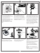
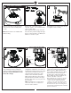
1 2 ON ON OFF OFF 3 Mounting bracket Before you begin installing the fan, Switch power off at Service panel and lock service disconnecting means to prevent power from being switched on accidentally. When the service disconnecting means cannot be locked, securely fasten a warning device, such as a tag, to the service panel. Use AC 120V/60HZ power supply only. 4 Downrod Mount Installation Before installing this fan make sure the outlet box is properly installed to the house structure.
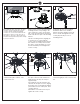
7 SAFETY CABLE INSTALLATION 8 9 Wall switch White (Neutral) Power source Tab Black (Live) Ground/Green Lag screw Black Blue Safety cable White Slot Washer Lock washer Install ball end of downrod into mounting bracket opening. Align (engage) slot on ball with tab on mounting bracket. Warning: Failure to align slot on ball with tab may result in serious injury.
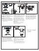
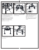
12 Flush Mount Installation 13 14 Side cover Remove every other screws from yoke located on top of fan assembly. Keep screws. Note: Flush mount is not available with vaulted ceiling. 15 Remove side covers from canopy exposing 4 holes. 2 closed holes and 2 open “L” shape holes. Place rubber pad and canopy over lead wire and safety cable and align the larger holes in canopy and holes on rubber pad with the set screws on yoke. 16 SAFETY CABLE INSTALLATION Reinstall the 3 set screws remove in step 12.
18 19 Grounded wires 20 Ungrounded wires Blade After making the wire connections, the wires should be spread apart with the grounded conductor and the equipment-grounding conductor on one side of the outlet box and ungrounded conductor on the other side of the outlet box. The splices after being made should be turned upward and pushed carefully up into the outlet box.
24 25 LED light fixture 26 Glass Reverse switch Connect white wire from fan to white wire from LED light fixture and then connect blue (or black) wire from fan to black (or blue) wire from LED light fixture. Attach LED light fixture onto the light pan, aligning the keyhole slots on the LED light fixture with the preassembled screws on the light pan. Twist clockwise till lock. Reinstall the screw removed in step 23. Tighten all screws securely.
Trouble Shooting or wiring. In some cases, these installation errors may be mistaken for defects. If you experience any faults, installation, please call our Customer Service Center at the number printed on your parts list insert sheet. Warning means to prevent power from being switched on accidentally. When the service disconnecting means cannot be locked, securely fasten a prominent warning device, such as a tag, to the service panel. Trouble 1. If fan does not start: Suggested Remedy 1.
Nov.