
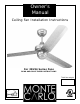
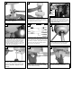
Installation Guide


C
arefully lift fan assembly onto mounting
b
racket. Rotate fan so that the notch on the
ball engages the ridge in the mounting bracket.
T
his will allow hands-free wiring.
8
7
R
emove any shipping stabilizers if
present. Attach blade assembly to
motor using the motor screws and
washers provided. Tighten screws
securely
.
13
Make wire connections to power source using
w
ire nuts provided. Make sure that no filiments
are outside of the wirenut. After making the
wire connections, the wires should be spread
apart with the grounded conductor and the
equipment-grounding conductor on one side of
the outlet box and ungrounded conductor on
the other side of the outlet box.
10
For pullchain controls, follow diagram above.
M
ake sure that all exposed wiring is secured
i
nside wire nuts. Note: Wires from house may
vary in color and may not include ground wire.
After wiring is conplete, gently push wires into
junction box with wire nuts pointing upward.
Refer to point 3 of safety tips.
11
House
Fan
B
lack
W
hite
G
reen
B
lack
White
Green(downrod)
G
reen(Bracket)
B
lue
Tighten both yoke set screws to fur-
ther secure downrod.
Fan and light kit combinations over 70 lbs, in
b
oth flush and downrod mode the safety cable
m
ust be installed into the house structure
beams using the 3” lag screws,washers, and
l
ock washers. provided. Make sure that when
t
he safety cable is fully extended the lead wires
are longer than the cable and no stress is
p
laced on the lead wires.
9
Safety cable installation
Safety Cable
L
ag Screw
safety
cable
3” lag
s
crew
l
ock
washer
washer
R
emo
ve 3 screws from the switch
housing plate and save to re-install
into the switch housing.
Install the switch housing using the
3 screws previously remo
ved.
15
14
Raise the canopy up and align the two holes in
the canopy with the two holes in the hanger
bracket. Secure with two screws provided.
12