
Installation Sheet

5
11 12 13
14 15 16
© 2022 Monte Carlo Fan Collections
2/2022
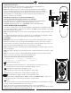
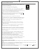
Make wiring connections using wire connectors provided as indicated above.
Brown wire from fan to Brown wire from receiver marked Motor U.
Gray wire from fan to Gray wire from receiver marked Motor V.
Orange wire from fan to Orange wire from receiver marked Motor W.
White wire from fan marked “For light” to White wire from receiver marked “For light”.
Blue wire from fan marked “For light” to Blue wire from receiver marked “For light”.
White (Neutral) wire from house to White wire from remote marked AC IN N.
Black (Live) wire from house to Black wire from remote marked AC IN L.
Connect all green grounded wires to Grounded wire from House.
Make sure that no filaments are outside of the wire connectors.
Insert the remote receiver into mounting bracket.
After making the wire connections, the wires should be spread apart with the grounded conductor and the equipment-grounding conductor on one
side of the outlet box and ungrounded conductor on the other side of the outlet box. The splices after being made should be turned upward and
pushed carefully up into the outlet box.
Place the wi-fi antenna outside canopy and stick/fix it onto ceiling.
Caution: The installation has to be complete before operate the fan. Receiver has to be used on the fan and cannot be bypassed.
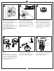
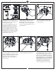
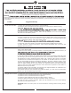
Partially loosen one and remove one
preassembled step screw from mounting
bracket (Do not remove the other set
screws). Save the screw.
Lift canopy up, aligning its keyhole slot
with the preassembled step screw on
mounting bracket and twist clockwise to
lock in place. Reinstall the other step
screw and tighten the screws securely.
Attach canopy bottom cap onto canopy
by aligning its holes with the step screws
on mounting bracket and fix it with the
magnet embraced in the cap.
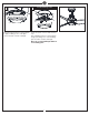
Loosen 2 and remove 1 preassembled
screw from the plate on motor. Save
screw for later use.
Attach the light pan onto the plate on
motor, Place light pan over the lead wires
from fan, aligning the keyhole slots on the
light plate with the preassembled screws
on the plate. Twist clockwise till lock.
Reinstall the other screw. Tighten all
screws securely.
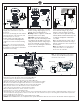
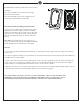
Loosen 2 and remove 1 preassembled
screws from light pan. Keep screw.
Connect white wire from fan to white wire
from LED light fixture and then connect
blue (or black) wire from fan to black (or
blue) wire from LED light fixture. Be sure
plugs connection clasped together firmly.
Attach LED light fixture onto the light pan,
aligning the keyhole slots on the LED light
fixture with the preassembled screws on
the light pan. Twist clockwise till lock.
Reinstall the screw which was just
removed. Tighten all screws securely.
Install the blade by using the set screws
provided. Align the 3 holes on in the
blade with the screw holes in the motor
and install the screws securely. Tighten
screws securely. Repeat this process for
remaining blades.
Blade
Light pan
Plate on motor
Step screw
Step screw
Install LED Light Fixture