Owner’s Guide and Installation Manual 3NDR54XXD Series Fan ETL Model NO. : 3NDR54XXD Attach sales receipt to this card and retain as your proof of purchase DATE OF PURCHASE: RETAILER NAME: MODEL NUMBER: RETAILER ADDRESS: To register your fixture, please visit our website www.montecarlofans.com 6.2 kgs 13.
Cautions and Warnings WARNING: TO REDUCE THE RISK OF FIRE, ELECTRIC SHOCK, OR INJURY TO PERSONS, OBSERVE THE FOLLOWING READ AND SAVE THESE INSTRUCTIONS Installation work and electrical wiring must be done by qualified person(s) in accordance with applicable codes and standards (ANSI/NFPA 70) including fire-rated construction. Use this unit only in the manner intended by the manufacturer. If you have any questions contact the manufacturer.
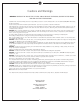
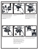
1 2 ON 3 ON Mounting bracket OFF OFF Before you begin installing the fan, Switch power off at Service panel and lock service disconnecting means to prevent power from being switched on accidentally. When the service disconnecting means cannot be locked, securely fasten a warning device, such as a tag, to the service panel. Use AC 120V/60HZ power supply only. 4 Before installing this fan make sure the outlet box is properly installed to the house structure.
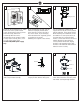
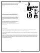
7 8 SAFETY CABLE INSTALLATION 9 Tab Keeper pin Cross pin Lag screw Safety cable Slot Washer Lock washer Slip downrod into motor housing yoke, aligning holes and install cross pin and keeper pin. Insert cross pin through yoke and downrod until point appears on the other side, and insert keeper pin on cross pin. Pull the downrod up tight against the cross pin, and then evenly tighten the downrod set screws on motor housing yoke. Place yoke cover on top housing of fan.
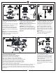
12 13 14 Top plate Blade Plate on motor Blade bracket Light pan Place blade on blade bracket and then place top plate on blade, aligning each of the holes as shown and install the blade with top plate onto blade bracket with screws provided, tighten all screws securely. Repeat this process for remaining blades. Loosen 2 and remove 1 preassembled screw from the plate on motor. Save screw for later use.
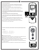
Remote Controller Operation Remove the battery cover from the remote control transmitter and install battery. Replace the cover. This remote uses 12V battery, Duracell MN21 / Evereday A23 / GP 23A all 12V. Model:RH787T FCC ID:CHQRH787T This device complies with part 15 of the FCC rules.Operation is subject to the following two conditions. (1)This device may not cause harmful interference and(2)This device must accept any interference received,Including interference that may cause undesired operation.
Install Transmitter wall mount cradle with 2 screws provided. Move the trim plate out from wall mount cradle and install the wall mount cradle with 2 screws provided. Replace the trim plate. Trim plate Wall mount cradle The receiver provides the following protective functions Lock protection- The DC motor has a build-in safety feature against blade obstruction during operation. If something obstructs the fan blades the motor will stop operation after 30 seconds of interruption.
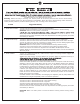
Trouble Shooting or wiring. In some cases, these installation errors may be mistaken for defects. If you experience any faults, installation, please call our Customer Service Center at the number printed on your parts list insert sheet. Warning: Before servicing or cleaning unit, Switch power off at Service panel and lock service disconnecting means to prevent power from being switched on accidentally.
Mar.