
Installation Guide


4
© 2016 Monte Carlo Fan Company
11/2016
7 8 9
10
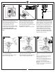
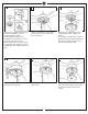
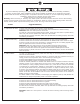
Slip blade onto blade bracket. Align the holes
in the blade with the holes in blade bracket
and install blade set screws provided. Do not
over tighten.
Repeat this process for remaining blades.
Install ball end of downrod into mounting
bracket opening. Align (engage) slot on
ball with tab on mounting bracket.
Warning: Failure to align slot on ball with
tab may result in serious injury.
Important: If using the angle mount,
make sure open end of mounting bracket
is installed facing the higher point of the
ceiling and make sure the ceiling angle is
not steeper
than 25º.
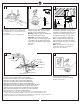
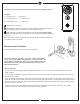
For Canadian installation and for USA fan
and light kit combinations over 35 lbs, in
both flush and downrod modes the safety
cable must be installed into the house
structure beams using 1.5” lag screws,
washers and lock washers provided.
Make sure that when the safety cable is
fully extended the lead wires are longer
than the cable and no stress is placed on
the lead wires.
Note: If Installing The Secondary Support
Safety Cable in the U.S., Do Not Remove
Knockouts In The Outlet Box.
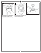
Loosen one and remove one
preassembled screw from mounting
bracket. Save screw.
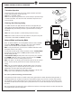
Make wiring connections using wire connectors provided as indicated above.
Red from fan to Red from remote marked Motor 1.
Purple from fan to Purple from remote marked Motor 2.
Gray from fan to Gray from remote marked Motor 3.
Blue from fan to Blue from remote marked FOR LIGHT.
White from fan to White from remote marked FOR LIGHT.
White (Neutral) from house to White from remote marked AC IN N.
Black (Live) from house to Black from remote marked AC IN L.
Connect all green grounded wires to Grounded wire from House.
Make sure that no filaments are outside of the wire connectors.
Insert the remote receiver into mounting bracket.
After making the wire connections, the wires should be spread apart with the grounded
conductor and the equipment-grounding conductor on one side of the outlet box and
ungrounded conductor on the other side of the outlet box. The splices after being made should
be turned upward and pushed carefully up into the outlet box.
Blue (For Light)
White (For Light)
Red (Motor 1)
Purple (Motor 2)
Gray (Motor 3)
Black (AC IN L)
White (AC IN N)
Green/Ground
Wall Switch
Ground/Green
Black (Live)
White (Neutral)
Power source
Receiver
Tab
Downrod
Slot
SAFETY CABLE INSTALLATION
Lag screw
Safety cable
Washer
Lock washer
11