
Installation Guide


4
7 8 9
10 11
© 2020 Monte Carlo Fan Collections
12/2020
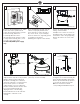
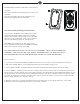
Thread lead wires and safety cable from
motor assembly through downrod.
Install downrod. Slip downrod into motor
housing yoke, aligning holes and install cross
pin and keeper pin.
Insert cross pin through yoke and downrod
until point appears on the other side, and
insert keeper pin on cross pin.
Pull the downrod up tight against the cross
pin, and then evenly tighten the downrod set
screws on motor housing yoke.
Warning: Cross pin and keeper pin must be
installed securely, failure to install them will
result in serious injury.
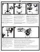
Place top cover, downrod sleeve,
decorative ring and canopy over downrod,
and then replace the hanger ball with pin
and set screw. Tighten it securely.
Warning: Make sure the pin is installed
well on hanger ball with downrod.
Note: For the downrod sleeve, make sure
the side with an “UP” label is installed
upward. The label is removable.
Note: Downrod sleeve is not available if
use the shorter 4” downrod
Install ball end of downrod into mounting
bracket opening. Align (engage) slot on
ball with tab on mounting bracket.
Warning: Failure to align slot on ball with
tab may result in serious injury.
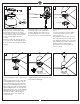
Important: If using the angle mount,
make sure open end of mounting bracket
is installed facing the higher point of the
ceiling and make sure the ceiling angle is
not steeper than 15º. Longer downrod
may be necessary allowing the fan blades
to rotate without obstructions.
For Canadian installation and for USA fan
and light kit combinations over 35 lbs, in
both flush and downrod modes the safety
cable must be installed into the house
structure beams using 3” lag screws,
washers and lock washers provided.
Make sure that when the safety cable is
fully extended the lead wires are longer
than the cable and no stress is placed on
the lead wires.
Note
: If Installing The Secondary Support
Safety Cable in the U.S., Do Not Remove
Knockouts In The Outlet Box.
Make wiring connections using wire connectors provided as indicated above.
Brown wire from fan to Brown wire from receiver marked Motor U.
Gray wire from fan to Gray wire from receiver marked Motor V.
Orange wire from fan to Orange wire from receiver marked Motor W.
White wire from fan marked “For light” to White wire from receiver marked “For light”.
Blue wire from fan marked “For light” to Blue wire from receiver marked “For light”.
White (Neutral) wire from house to White wire from remote marked AC IN N.
Black (Live) wire from house to Black wire from remote marked AC IN L.
Connect all green grounded wires to Grounded wire from House.
Make sure that no filaments are outside of the wire connectors.
Insert the remote receiver into mounting bracket.
After making the wire connections, the wires should be spread apart with the grounded conductor
and the equipment-grounding conductor on one side of the outlet box and ungrounded conductor
on the other side of the outlet box. The splices after being made should be turned upward and
pushed carefully up into the outlet box.
Cross pin
Keeper pin
Pin
Canopy
Decorative ring
Downrod sleeve
Tab
Slot
SAFETY CABLE INSTALLATION
Lag screw
Safety cable
Washer
Lock washer
Orange
Brown
Grey
White
White
Black
Black
Receiver
White
Blue
Ground/Green
Ground/Green
Wall switch
Power source
Top cover
UP