
Specifications


Intel
®
810E2 Chipset Platform
R
Design Guide 107
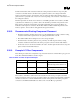
Figure 66. RAMDAC Component and Routing Guidelines
RAMDAC
VCCDACA1/
VCCDACA2
VCCDA
RED
Graphics
Chip
Pixel
Clock
(From
DPLL)
Cf
Lf
LC
Filter
1.8V Board
Power Plane
Place LC filter components &
high frequency de-coupling
capacitors as close to the power
pins as possible.
1.8V Board
Power Plane
GREEN
Blue
VSSDACA
Analog
Power Plane
1.8V
IREF
IWASTE
Place the
Reference
Resistor in Close
Proximity to the
IREF Pin
Rset
VGA
ramdac4.vsd
1.8V Board
Power Plane
Rt
D2
D1
C1
C2
FB
pi Filter
Red Route
37.5 Ω Route
75 Ω Routes
1.8V Board
Power Plane
Rt
D2
D1
C1
C2
FB
pi Filter
Green Route
37.5 Ω Route
75 Ω Routes
1.8V Board
Power Plane
Rt
D2
D1
C1
C2
FB
pi Filter
Blue Route
37.5 Ω Route
75 Ω Routes
Place Diodes Close
to RGB Pins
Avoid Routing
Toggling Signals in
this Shaded Area.
via Straight Down to the Ground Plane
- Match the RGB Routes
- Make Spacing Between the RGB Toutes a Min. of 20 mils
Place the pi-Filter in close proximity
to the VGA connector.
NOTES: Diodes D
1
, D
2
are clamping diodes and may not be necessary to populate.