
Specifications


Intel
®
810E2 Chipset Platform
R
Design Guide 105
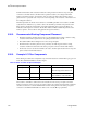
3.25. RAMDAC/Display Interface
The following figure shows the interface of the RAMDAC analog current outputs with the display. Each
DAC output is doubly-terminated with a 75-Ω resistance; one 75-Ω resistance from the DAC output to
the board ground and the other termination resistance exists within the display. The equivalent DC
resistance at the output of each DAC output is 37.5 Ω. The output current of each DAC flows into this
equivalent resistive load to produce a video voltage without the need for external buffering. There is also
an LC pi-filter that is used to reduce high-frequency glitches and noise, and reduce EMI. To maximize
the performance, the filter impedance, cable impedance, and load impedance should be the same. The LC
pi-filter consists of two 3.3 pF capacitors and a Ferrite bead with a 75-Ω impedance at 100 MHz. The LC
pi-filter is designed to filter glitches produced by the RAMDAC while maintaining adequate edge rates to
support high-end display resolutions.
Figure 65. Schematic of RAMDAC Video Interface
RAMDAC
VCCDACA1/
VCCDACA2
VCCDA
RED
Graphics
Chip
Pixel
Clock
(From
DPLL)
Cf
Lf
LC
Filter
1.8V Board
Power Plane
Display PLL Power
Connects to this
Segmented Power
Plane
1.8V Board
Power Plane
1.8V Board
Power Plane
Rt
D2
D1
C1
C2
FB
pi Filter
1.8V Board
Power Plane
Rt
D2
D1
C1
C2
FB
pi Filter
1.8V Board
Power Plane
Rt
D2
D1
C1
C2
FB
pi Filter
GREEN
Blue
VSSDACA
Analog
Power Plane
1.8V
IREFIWASTE
Ground Plane
Rset 1% Reference
Current Resistor
(metal film)
Video
Connector
Graphics Board
Red
Green
Blue
Coax
Cable
Zo=75Ω
75Ω
75Ω
75Ω
Display
Termination Resistor, R 75Ω 1%
(metal film)
Diodes D1, D2: Schottky Diodes
LC Filter Capacitors, C1, C2: 3.3 pF
Ferrite Bead, FB: 7 Ω @ 100 MHz
(Recommended part: muRata
BLM11B750S)
ramdac3.vsd
NOTES: Diodes D
1
, D
2
are clamping diodes and may not be necessary to populate.