
Specifications


Intel
®
810E2 Chipset Platform
R
104 Design Guide
3.24.5. Custom Solutions
As long as filter performance as specified in the previous “Filter Specification” figure and other
requirements outlined in Section 3.24.1. are satisfied, other solutions are acceptable. Custom solutions
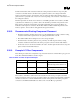
should be simulated against a standard reference core model, which is shown in the figure below.
Figure 64. Core Reference Model
PLL1
PLL2
Processor
0.1 ohm
120pF 1K ohm
0.1 ohm
NOTES:
1. 0.1
Ω resistors represent package routing1.
2. 120 pF capacitor represents internal decoupling capacitor.
3. 1 k
Ω resistor represents small signal PLL resistance.
4. Be sure to include all component and routing parasitics.
5. Please sweep across component/parasitic tolerances.
6. To observe IR drop, use DC current of 30 mA and minimum VCC
CORE
level.
1 For other modules (interposer, DMM, etc), adjust routing resistor if desired, but use minimum numbers.