
Specifications


Intel
®
810E2 Chipset Platform
R
Design Guide 101
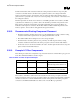
The filter specification is graphically shown in the following figure.
Figure 61. Filter Specification
0dB
-28dB
-34dB
0.2dB
x dB
1 MHz 66 MHz fcorefpeak1HzDC
passband
high frequency
band
x = 20.log[(Vcc-60mV)/Vcc]
filter1.vsd
NOTES:
1. Diagram not to scale.
2. No specification for frequencies beyond fcore.
3. fpeak, if it exists, should be less than 0.05 MHz.
Other requirements:
• Filter should support DC current > 30 mA.
• Shielded type inductor to minimize magnetic pickup.
• DC voltage drop from VCC to PLL1 should be < 60mV, which in practice implies series
R < 2
Ω; also means pass band (from DC to 1Hz) attenuation < 0.5dB for
VCC = 1.1V, and < 0.35dB for VCC = 1.5V.