1N Wireless Broadband Router User Guide
11N Wireless Broadband Router User Guide Copyright Statement is the registered trademark of Monoprice, Inc. All the products and product names mentioned herein are the trademarks or registered trademarks of their respective holders. Copyright of the whole product as integration, including its accessories and software, belongs to Monoprice, Inc. Without the permission of Monoprice, Inc., any individual or party is not allowed to copy, plagiarize, reproduce or translate it into other languages.
11N Wireless Broadband Router User Guide Contents CHAPTER 1 PRODUCT INTRODUCTION ....................................... 1 1.1 Package Contents ....................................................... 1 1.2 LED Indicators and Port Description .............................. 2 CHAPTER 2 PRODUCT INSTALLATION ......................................... 4 CHAPTER 3 PREPARING TO ACCESS THE INTERNET............... 6 3.1 Setup the Network Configuration on Your PC .................. 6 3.2 Log in to the Router .......
11N Wireless Broadband Router User Guide 6.1 DHCP Server ............................................................ 37 6.2 DHCP Client List ........................................................ 38 CHAPTER 7 VIRTUAL SERVER ....................................................... 39 7.1 Port Range Forwarding .............................................. 39 7.2 DMZ Settings ........................................................... 41 7.3 UPNP Settings ..................................................
11N Wireless Broadband Router User Guide
Chapter 1 Product Introduction Thank you for purchasing the Monoprice Wireless N Broadband Router! This easy-to-use router provides a simple configuration interface, which allows you to configure it with ease. It is based on the latest IEEE802.11n standard and is backwards compatible with devices using the IEEE802.11b/g standards. The Monoprice wireless router provides router, wireless AP, four-port switch, and firewall functions in one package.
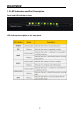
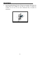
1.
Back panel ports Back panel port description 3
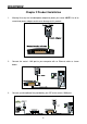
Chapter 2 Product Installation 1. Warning! Use only the included power adapter to power your router. NOTE: Use of an unmatched power adapter could cause damage to this product. 2. Connect the router's LAN port to your computer with an Ethernet cable as shown below. 3. Connect your broadband line provided by your ISP to the router's WAN port.
4. Insert the included software CD into the CD drive of your computer. After the disc has loaded double click the Setup icon and follow the instructions to complete the installation. You can also use the router's Web-based Utility to complete the configuration.
Chapter 3 Preparing to Access the Internet 3.1 Setup the Network Configuration on Your PC Network Configuration under windows XP 1. Right click My Network Places on your computer desktop and select Properties. 2. Right click Local Area Connection and select Properties.
3. 4. Select Internet Protocol (TCP/IP) and click Properties. Select Use the following IP address and enter the IP address, Subnet mask, Default gateway as follows: IP Address: 192.168.0.XXX: (XXX is a number from 2~254) Subnet Mask: 255.255.255.0 Gateway: 192.168.0.1 DNS server: You should input the DNS server address provided by your ISP. Otherwise, you can enter 192.168.0.1. Click OK to save the configurations.
Network Configuration under windows 7 1. Click the network icon on the lower right corner of your computer desktop, and then click Open Network and Sharing Center. 2. Click Change adapter settings on the left side of the window.
3. Right click Local Area Connection and select Properties. 4. Double click Internet Protocol Version 4 (TCP/IPv4).
5. Select Use the following IP address and enter the IP address, Subnet mask, Default gateway as follows: IP Address: 192.168.0.XXX: (XXX is a number from 2~254) Subnet Mask: 255.255.255.0 Gateway: 192.168.0.1 DNS server: You should input the DNS server address provided by your ISP. Otherwise, you can enter 192.168.0.1. Click OK to save the configurations. 3.
3.3 Fast Internet Access Two kinds of fast access methods are provided on the router's web-based utility: ADSL Dial-up and DHCP. If you select ADSL Dial-up, you need to enter the access account name and access password for your ADSL account (provided by your ISP), as well as the wireless password (default is 12345678), then click Ok to complete the settings.
If you select DHCP, you only need to enter the wireless password (default is 12345678) and click Ok to complete the settings.
broadband ISP. For other access methods, please refer to WAN settings in chapter 4.The wireless password can only consist of 8 characters, the default is 12345678, and you can modify it when necessary. 3.4 Fast Encryption The router provides two encryption setting screens, one is simple and easy, the other is advanced. For instructions on using the advanced setting, please refer to chapter 5.2. Simple and easy setup: Log on to the router's web-based utility and choose the encryption method for the router.
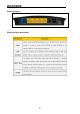
Chapter 4 Advanced Settings 4.1 System Status Click Advanced Settings > System Status to view the router's WAN port and system status. Connection status: Displays the router's WAN connection status. Disconnected: Indicates the router's WAN port hasn't been connected with a network cable. Connecting: Indicates the router's WAN port is obtaining an IP address. Connected: Indicates the Router is properly connected to the ISP. WAN IP: IP address obtained from ISP. Subnet mask: Obtained from ISP.
LAN MAC address:Displays the Router's LAN MAC address. WAN MAC address:Displays the Router's WAN MAC Address. System time:Displays the system's updated time Connected client:Displays the number of the connected computers (normally Software version:Displays the Router's software version. Hardware version:Displays the Router's hardware version. displays the number of clients whose IP addresses are obtained via DHCP server). 4.
Mode: Shows your current connection mode. Access Account: Enter the account provided by your ISP. Access Password: Enter the password provided by your ISP. MTU: Maximum Transmission Unit. This is the size of the largest data packet that can be sent over the network. The default value is 1492. Do NOT modify it unless necessary. If a specific website or web application software cannot open or be enabled, you can try to change the MTU value to 1450, 1400, etc.
The “Connect on Fixed Time” setting goes into effect only when you have set the current time in “Time settings” from the “System tools” menu. Static IP If your ISP provides you with a static IP, please choose static IP. You will need to enter the IP address, subnet mask, gateway, DNS server, and alternate DNS server provided by your ISP or network administrator. Mode: Shows your current connection mode. IP address: Enter the WAN IP address provided by your ISP.
PPTP Mode: Shows your current connection mode. PPTP server address: The IP address or domain name of the destination server, used to specify the destination address, which is needed for a PPTP connection. Username/Password: Used to log in to the PPTP server. Address mode: Sets the router's IP address mode. You can select either Dynamic or Static. If your ISP doesn't provide a fixed IP address, please select Dynamic. IP address: Enter the IP address provided by your ISP.
should be, contact your local ISP for assistance. All the above values are provided by your ISP. L2TP Mode: Shows your current connection mode. L2TP server address: The IP address or domain name of the destination server, used to specify the destination address, which is needed for a L2TP connection. Username/Password: Used to log in to the L2TP server. Address mode: Set the router's IP address mode, you can select either Dynamic or IP address: Enter the IP address provided by your ISP.
Click Advanced settings > LAN settings to configure the router's IP address and Subnet Mask. LAN MAC address: The router's LAN MAC address, which cannot be changed. IP address: The router's LAN IP address (not your PC's IP address).The default Subnet Mask: The router's LAN Subnet Mask. The default value is 255.255.255.0 value is 192.168.0.1. You can change it when necessary. NOTE: Once you modify the IP address, you need to remember it for next time you log in to the web-based utility. 4.
MAC Address: Set the router's WAN MAC address. Clone MAC Address: Clicking this button changes the router's WAN MAC address from the default to the MAC address of the PC you are currently using. Don't use this button unless your PC's MAC address is the one bound by your ISP. Restore Default MAC: Restores the router's WAN MAC to default settings. 4.5 DNS Settings Click Advanced settings > DNS settings to view the following screen. DNS stands for Domain Name System (or Service).
Primary DNS address: Enter the necessary DNS address provided by your ISP. Alternate DNS address: Enter the secondary DNS address if your ISP provides one (this is optional). NOTE: After the settings are completed, reboot the router to activate the modified settings. 4.6 WAN Medium Type Click Advanced settings > WAN medium type to configure the type of WAN the router will utilize (wired or wireless). Wired WAN: In this mode, the cable is directly connected to the WAN port.
service or you want to use the router to expand your wireless signal coverage. SSID: SSID (Service Set Identifier) is the identity of the wireless device. You can only access the ISP's network by entering the correct SSID of the ISP's wireless device. You can click the Open scan button to let the router automatically search for any available SSIDs. The SSID can also be the SSID of the primary wireless device when using the router as a wireless bridge.
Enable Bandwidth Control: Enable or disable the internal IP bandwidth control. The default is disabled. IP Address: The IP address range of the connected client computers whose traffic you want to control. It can be a single IP address or IP address range. Upload/Download: Specifies the direction in which traffic is to be controlled for the selected IP addresses, either uploading or downloading.
1. Enter 100 - 100 in the IP address field 2. Select Upload in the Upload/Download field. 3. Enter 10 - 15 in the Bandwidth range field 4. Click the box next to the Enable field so that it has a check mark in it. 5. Click the Add to list button. 6. Click Ok to finish setting the upload rule settings. Next add a download rule as shown in the following image using the following steps, as illustrated in the next image: 1. Enter 100 - 100 in the IP address field 2. Select Download in the Upload/Download field.
Example 2 The following two screen shots depict how to set an upload rate limit of 20-30 KBytes/s and a download rate limit of 100-120 KBytes/s for computers within the IP address range 192.168.0.2 to 192.168.0.254.
These values are set using the same method as in Example 1. 4.8 Traffic Statistics The Traffic Statistics screen is used to display the bandwidth used by each connected PC. Enable Traffic statistics: Check this box to allow the router to calculate the traffic used by each computer connected to the LAN. Usually it is best to leave this disabled to improve the router's data packet processing ability, and the default is disabled.
refresh automatically every five minutes. IP address: the IP address of the computer whose traffic is being calculated. Uplink rate: the data sending speed per second in KBytes/s. Downlink rate: the data receiving speed per second in Kbytes/s. Sent message: the number of data packets sent out through the router. Sent Bytes: the total volume of data that is sent out through the router. Received message: the number of data packets received through the router.
port to work at maximum speed. This will result in lost a lost data if an error occurs. It is better to choose the AUTO option so that the router can dynamically react to fluctuations in signal strength and reliability.
Chapter 5 WLAN Settings 5.1 Wireless Basic Settings Enable wireless function: When selected it enables the router's wireless features. When not selected, all wireless features and functions are disabled. Wireless Working mode: Select between the two possible wireless modes: Wireless Access Point (AP) and Network Bridge (WDS). Wireless Access Point (AP) Network Mode: Select one of the modes from the drop-down list: 11b mode :Use this mode if you have only Wireless-B clients in your network.
devices must be manually configured to use the router's SSID. This is enabled by default. AP Isolation: This option is disabled by default, and it is recommended that you leave it disabled. When enabled, wireless clients connected via the primary SSID and wireless clients connected via secondary SSID are isolated and cannot communicate with each other. Enable this option only if you want to operate two completely separate wireless LANs, each with their own separate SSID.
Network Bridge (WDS) Settings WDS (Wireless Distribution System) is used to expand the wireless coverage area for an existing network. AP MAC address: Input the MAC address of another (opposing) wireless router whose coverage you want to expand. Example: This example bridges two W368R routers.
1. If you know the connecting router's MAC address, enter it into the AP MAC address field and click Ok. 2. You can also obtain the MAC address by scanning for the router's signal. a) Click Open scan to get a list of available routers. Select the router you want to connect to and click the Ok button on the dialog box. The corresponding wireless MAC address will be added to the AP MAC address field automatically.
b) After the MAC address is added, click Ok. 3. After completing the above steps, repeat the process with the other W368R router.
channel, encryption method, and password are the same on each connected router. 5.2 Wireless Security Settings With the wireless security function, you can prevent others from connecting to your wireless network and using the network resources without your consent. Meanwhile, you can also block illegal users from intercepting or intruding into your wireless network. 5.2.
WPS/PBC negotiation between them. When the WPS connection is completed, the LED indicator will be continuously lit. To add more clients, repeat the above steps.) PIN: If this option is enabled, you need to enter a wireless client's PIN code in the field and use the same code for the WPS client. Reset OOB: Press this button, the WPS client will be in an idle state, and the WPS indicator will turn off.
often it should change the dynamic keys. 5.2.3 WPA2-PSK WPA2 (Wi-Fi Protected Access version 2) provides even higher security than the use of basic WPA. WPA Algorithms: Allows the use of TKIP (Temporal Key Integrity Protocol), AES (Advanced Encryption Standard), or both. Key: Enter a pass phrase that consists of 8-63 ASCII characters. Key Renewal Interval: Set the key's renewal period, which tells the device how often it should change the dynamic keys.
5.2.4 WEP The WEP (Wired Equivalent Privacy) is an encryption method that encrypts the data transferred wirelessly between devices to prevent unauthorized users from intercepting or invading the wireless network. WEP security, based on RC4 data encryption technology, provides data confidentiality, integrity, and authentication for wireless communications. Security Mode: Select the corresponding security mode from the drop-down menu. The Open option is more secure and is preferred over the Shared method.
5.3 Wireless Access Control Wireless access control is based on the MAC address to permit or forbid specific clients' access to the wireless network. MAC address filter: The Permit option allows the specified clients in the list access to the wireless network, while the Forbid option prevents the specified clients in the list from accessing the wireless network. Configure MAC address: Input the MAC addresses of the wireless clients to MAC Address list: Displays the filtered MAC addresses.
MAC address: Shows the MAC addresses of the clients connected to the router. Bandwidth: Shows the channel bandwidth of the currently connected wireless clients.
Chapter 6 DHCP Server 6.1 DHCP Server The DHCP (Dynamic Host Control Protocol) is used to assign an IP address to the computers on the LAN/private network. When you enable the DHCP Server, the DHCP Server will automatically allocate an unused IP address from the IP address pool to the requesting computer. You must specify the starting and ending address for the IP Address pool. DHCP server: Check the Enable box to enable the DHCP server.
6.2 DHCP Client List The DHCP client list displays client computer IP addresses, MAC addresses, host names, and other information assigned by the DHCP server. You can manually enter the IP and MAC address to convert an IP into a static assignment for the specified client. IP address: You can specify an IP address for static binding. MAC address: Enter the MAC address of the computer you want to give static binding. Click Add to add the entry in the list.
Chapter 7 Virtual Server 7.1 Port Range Forwarding Port Range Forwarding allows you to specify which IP address is to receive incoming data over specific ports. This is useful when running an application that will receive data from the internet on a specific port, or port range, without having first sent out data to the internet on the same port (e.g., when running a web server, ftp host, etc. Start/End port: Enter the starting and ending port numbers to be forwarded to the specific client computer.
area network. However, they are too big, and it's not convenient to physically transfer them. You can build a FTP server on your computer and set the router's port range forwarding to give your friends access to these files on your computer. For the purpose of this example, suppose that your FTP server (or your computer's static IP address) is 192.168.0.10 and you want your friends to access the server through the default port 21 using the TCP protocol. You would then perform the following steps: 1.
management port on the Remote Web Management screen to be any value except 80, e.g. 8080. Otherwise, there will be a conflict in disabling the virtual server. 7.2 DMZ Settings The DMZ Settings screen allows one local computer to be exposed to the Internet for use by a special-purpose service, such as Internet gaming or videoconferencing. DMZ hosting forwards all the ports at the same time to one PC.
With the UPnP (Universal Plug and Play) function, the internal client computer can request the router to process some special port switching, so as to allow an external client to use the resources of the internal host. Enable UPnP: Click the checkbox to enable the UPnP. NOTE: This function is enabled with Windows XP, Windows ME, and later, when using Direct-X 9.0 or later. This function is also enabled when using software that supports UPnP.
Chapter 8 Security Settings 8.1 Client Filter Settings You can enable client filtering to control a client computer's access to specific ports of the internet. Filter Mode: You can select either Permit only or Forbid only. Access Policy: Select an unused number from the drop-down list. Remark: Input a simple description of the configured filter rule (you may leave it blank if you wish). Start/End IP: Enter the Start IP and End IP address range.
Example 1: Prevent clients at IP addresses between 192.168.0.100 and 192.168.0.120 from accessing the Internet at any time. Example 2: Allow the computer with the IP address of 192.168.0.145 to access websites only between the hours 8:00 (8 am) and 18:00 (6 pm) on any day of the week.
8.2 MAC Address Filter You can also limit the client access to the internet using the MAC Address Filter. Filter mode: You can select either Permit only or Forbid only. Access Policy: Select an unused number from the drop-down list. Remark: Input a simple description of the configured filter rule (you may leave it blank if you wish).
Example 1: Prevent the computer with the MAC address of 00:E0:4C:69:A3:23 from accessing the internet between 8:00 (8 am) to 18:00 (6 pm) from Monday to Friday. Example 2: Allow the computer with the MAC address of 00:E4:A5:44:35:69 to access internet at any time of day from Monday to Friday.
8.3 URL Filter Settings You can use URL filtering to forbid client access to certain websites at a specified time and/or day of the week. Filter Mode: You can select either Disable or Forbid only. Access Policy: Select an unused number from the drop-down list. Remark: A simple description of the configured file. You can also leave it blank. Start/End IP: Enter the Start IP and End IP address range. URL character string: Enter text string(s) or keyword(s) that will be filtered.
Example: Prevent all computers on LAN from accessing baidu.com between 8:00 (8 am) and 18:00 (6 pm) from Monday to Friday. NOTE: Each access policy can filter only one domain name. So, if you want to filter multiple domain names, you need to set multiple access policies. 8.4 Remote Web Management This section allows the network administrator to manage the router remotely. If you want to access the router from outside of the local network, click the checkbox after Enable.
Enable: Check to enable remote web management. Port: The management port open to outside access. The default value is 80. IP Address: Specify the range of the IP addresses of the computers on the internet to allow remote management of the router's settings. NOTE: 1. If you want to log in the device's Web-based Utility via port 8080, you need to use the format of WAN IP address:port (for example http://220.135.211.56:8080) to implement remote login. 2.
Chapter 9 Routing Settings 9.1 Routing Table This page shows the router's core routing table. The main duty of a router is to look for the best path for every data packet and transfer that data packet to its destination station. To fulfill this function, many transferring paths, i.e. routing table, are saved in the router, for use when needed. 9.2 Static Routing This screen is used to set the router's static routing.
Gateway: The entry IP address of the next router. NOTE: 1. The gateway must be at the same net segment with the router's LAN IP. 2. If the destination IP address is a client's address, then the subnet mask must be 255.255.255.255. 3. If the destination IP address is an IP segment, then it must match the subnet mask. For example, if the destination IP is 10.0.0.0 then the subnet mask must be 255.0.0.
Chapter 10 System Tools 10.1 Time Settings This section is used to the router's internal clock. You can set it manually or obtain the GMT time from the Internet. Time zone: Select the time zone in which you are operating the router from the drop-down list. Customized time: Check this box to enable manual time setting, then enter the date and time in the appropriate fields. NOTE: When the Router is powered off, the time settings will be lost.
current IP address. DDNS: Click the radio button to Enable or Disable the DDNS service. Service provider: Select one of the available service providers from the drop-down list. If you haven't already registered with this service, click Sign up for registration. Username: Enter the Username for login to the DDNS provider. Password: Enter the password for login to the DDNS provider. Domain name: Enter the effective registered Domain Name.
Backup Setting: Click the Backup button to back up the Router's settings. You will be prompted to select a path in which to save the configuration file. Click the Save button to save the configuration files. Restore Setting: Click the Browse button to select the configuration file you wish to restore.
Click the “Restore” button to restore previous settings. 10.4 Restore to Factory Default This screen allows you to restore all settings to the factory default values.
Restore: Click this button to restore to default settings. Factory default settings: Password: NULL (the default password displays as null) IP address: 192.168.0.1 Subnet mask: 255.255.255.0 NOTE: After restoring to default settings, please restart the router to make the default settings effective. 10.5 Upgrade When updated firmware is available, you can upgrade the router's internal software to obtain improved performance and functionality. You can check for firmware updates at the http://www.
completed, the router will reboot automatically. 10.6 Reboot the Router Reboot the router to make a configuration take effect. The router will cut its WAN connection automatically after rebooting. Reboot the router: Click this button to reboot the router. 10.7 Password Change On this screen you can set a new password for the router. Changing passwords periodically is a good security practice.
Old password: Enter the old password. New password: Enter a new password. Confirm new password: Re-enter to confirm the new password. NOTE: The default password displays as null, users can log into the web-based utility without any authentication. To secure the router and your network, it is highly recommended that you change the initial password. 10.8 Syslog This screen allows you to review the system log.
LAN: Local Area Network. A LAN is a small network, which accesses a WAN through a Gateway. In most cases, the LAN is the network of computers in your home, which access the internet (WAN) through a router configured as a Gateway. MAC: Media Access Control. A MAC address is a unique identifier assigned to network interface devices. Each Network Interface Card (NIC), for example, has a unique MAC address.
Appendix 2 Product Features Supports IEEE 802.11n, IEEE 802.11g, IEEE 802.11b, IEEE 802.3, and IEEE 802.3u standards. High gain omni-directional antenna, with strong signals and long transmission distance. Wireless transmission rates up to 150 Mbps or 300 Mbps. Provides one 10/100 Mbps auto-negotiation Ethernet WAN port to connect to the Wide Area Network. Provides four 10/100 Mbps auto-negotiation Ethernet LAN ports to connect to the Local Area Network. Supports Auto MDI/MDIX.
Step 1: Check to see if the router is powered on and working correctly. After the device is powered on for a few seconds, the SYS indicator on the front panel should illuminate. If it is not lit, please contact us. Step 2: Check that the network cables are connected correctly and that the corresponding LED indicator illuminates. Sometimes, the indicator illuminates, but it does not mean it is functioning. Step 3: Run the “Ping” command and check to see if it can ping the router's LAN IP address 192.168.0.1.
is 192.168.0.10, input 10 in the IP address field. Step 5: Select the communication protocol used by your internal host: TCP, UDP, or Both. Step 7: Click Ok to activate the settings.
2. Right click Wireless Network Connections and select Properties. 3. Click Wireless Networks, select the network configuration in Preferred networks, then click the Remove button, as shown in the example below. Deleting the wireless configuration file under windows 7 1. Right click Network and click Properties.
2. Click Manage wireless networks on the left side of the window. 3. Select the corresponding configuration file, right click it, then select Remove network in the pop-up menu. Appendix 5 Regulatory Information EU Declaration or Declaration of Conformity Hereby, Monoprice declares that this Wireless Broadband Router is in compliance with the essential requirements and other relevant provisions of Directive 1999/5/EC.
reasonable protection against harmful interference in a residential installation. This equipment generates, uses, and can radiate radio frequency energy and, if not installed and used in accordance with the instructions, may cause harmful interference to radio communications. However, there is no guarantee that interference will not occur in a particular installation.