
Installation Guide


49
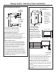
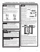
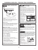
STEP 7 LEVEL REFRIGERATOR
All models have 4-point leveling. The front is
supported by leveling legs, the rear is supported by
adjustable wheels. Both are accessible from the front
of the refrigerator.
• To level the back of the refrigerator, turn the 7/16”
hex nut located above
the front wheels. Turn
clockwise to raise or
counterclockwise to lower
the refrigerator.
• For front leveling, use a
1-1/4” open-end wrench.
• Adjust height of refrigerator
to match installation cutout
opening 84-1/2”
(214.63 cm). The refrigerator should be level and
plumb with cabinetry.
NOTICE: The rear leveling wheels and front leveling
legs are limited to a maximum height adjustment of 1”
(2.54cm). If the installation requires more than 84-1/2”
(214.63 cm) height, the installer should elevate
the refrigerator on a sheet of plywood or runners.
Cabinetry trim could also be added across the top of
the opening to shorten the opening. If you attempt
to raise the refrigerator more than 1” (2.54 cm),
you will damage the front leveling legs and the
rear leveling wheels. Make adjustments in small
increments.
Installation Instruction - Stainless Steel Installation
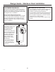
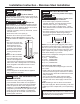
STEP 9 ADJUST DOOR SWING
NOTE: This refrigerator has a 3-position door stop.
When space does not allow the door to swing open
fully to 115°, you may change the door swing to a
90° opening. A 130° door swing option is available
for standard installation only. Skip this step if door
opening is satisfactory for your installation
situation.
• Open the door to view the bottom hinge. Note the
door stop pin locations. The pin is factory installed in
the 150° position.
• Close the door. From below, use pliers to unscrew
the door stop and reinstall into the 90° or 130°
position.
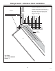
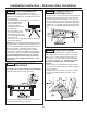
STEP 8 ALTERNATE ANTI-TIP
PROCEDURE
The refrigerator must be secured to prevent tipping.
• Raise the grille panel to access case trim.
• Use a 3/16” bit to drill four evenly spaced clearance
holes through the metal top case trim.
• Use a 1/16” bit to drill to pilot holes through the metal
clearance holes and into the wood soffit. The holes
should be centered in the soffit or a 3/4” (1.91 cm)
min. wood brace. The brace spanning the enclosure
must be securely fastened to cabinets on both sides.
• Install four, 1-1/2” drywall screws into the pilot holes.
• Drill screws into adjacent cabinets through side case
trim.
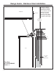
STEP 8 ALTERNATE ANTI-TIP
PROCEDURE (Cont.)
31-49171