
Owner's Manual


31-49140-2
18
Installation Instructions - Standard Installation
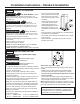
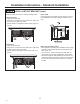
STEP 5 LEVEL UNIT
All models have 4-point leveling. The front is support-
ed by leveling legs; the rear is supported by adjustable
wheels. Both are accessible from the front of the unit.
• To level the back of the unit, turn the 7/16” hex nut
located above the front wheels. Turn clockwise
to raise or counterclockwise to lower the unit.
• For front leveling, use a 1-1/4” open-end wrench.
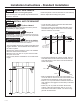
• Adjust height of unit to match installation cutout
opening 84-1/2”
(214.63 cm)
. The unit should be
level and plumb with cabinetry.
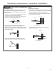
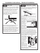
STEP 6 SECURE UNIT TO WALL
• The “L” rods can be found in the upper left and right
corners of the unit in the access compartment. Look
through the access compartment to make sure the
rods line up with the anti-tip bracket.
• There are 2 washers and a hair pin cotter per rod.
Remove the washers and hair pin cotter from the
end of the rod.
• Rotate and move the “L” rod into the slot in the
anti-tip bracket tab. Once it is in the slot, rotate the
“L” rod so the
hook portion is
pointing down.
The holes at
the front end of
the rod should
be in a vertical
position. Do this
to both sides.
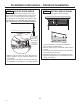
• Pull out on the
end of the rod to
make sure it is secure in the bracket.
• Locate the hole on the rod that is closest to the
unit. A hair pin cotter will be put through this hole
to secure the rod. If this hole appears to be too far
away for a snug fit against the unit, add the washers
one at a time until the pin will fit tightly into the hole.
• Align the straight section of the pin with the hole
from the underside of the rod. Push the pin up
until it snaps into
position. Pliers may
be used. NOTE:
The hair pin cotter
must be vertical
when this step
is completed to
ensure the “L” rod
is engaged in the
bracket.
• Check the rod for
tightness by pulling
forward. If the rod
moves, remove the
hair pin cotter and
place another washer on the rod. Reinsert the pin.
• Replace the grille panel.
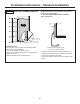
The rear leveling wheels and front leveling legs are
limited to a maximum height adjustment of 1”
(2.54 cm). If the installation requires more than
84-1/2”
(214.63 cm)
height, the installer should elevate
the unit on a sheet of plywood or runners. Cabinetry
trim could also be added across the top of the
opening to shorten the opening. If you attempt to raise
the unit more than 1” (2.54 cm), you will damage the
front leveling legs and the rear leveling wheels.
“L” Rod
Wall Bracket
“L” Rod