
Specification Sheet


For questions about your
appliance, please call 1-800-626-2000.
PAGE 3 OF 5 Product Specication Revised 6/20
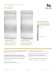
STANDARD INSTALLATION
HELPFUL TIPS
SIDE VIEW
W
24" (61.0 )
2 3/8"
(6)
4 1/2"
(11.4)
7/16"
(1.1)
Trim overlap
3 1/2"
(8.9)
FRONT VIEW
ELEC.
35 1/2"
(90.2)
2 5/16"
(5.9)
*83 1/2" min
*84 1/2" max
(212.1-214.6)
*Trim will overlap
additional 7/16"
3 1/2"
(8.9)
75
1/2
"
(191.8)
From floor
to bottom
of electrical
area
5 1/2"
(14.0)
9"
(22.9)
ZIFS360NXRH
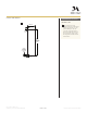
SIDE VIEW INSTALLED
WITH ANTI-TIP BRACKET
5"
(12.7)
5"
(12.7)
WATER
3 1/2"
(9.0)
81 1/2"
(207.0)
Use two
additional hole
locations at end
of brackets
Wall
Studs
Screws
mounted
into vertical
wall studs
C
Make sure
holes selected
are centered
on the studs
L
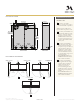
FRONT VIEW OF CUTOUT
WITH ANTI-TIP BRACKET
SIDE VIEW
W
24" (61.0 )
2 3/8"
(6)
4 1/2"
(11.4)
7/16"
(1.1)
Trim overlap
3 1/2"
(8.9)
FRONT VIEW
ELEC.
35 1/2" (90.2)
2 5/16"
(5.9)
*83 1/2" min
*84 1/2" max
(212.1-214.6)
*Trim will overlap
additional 7/16"
3 1/2"
(8.9)
75
1/2
"
(191.8)
From floor
to bottom
of electrical
area
5 1/2"
(14.0)
9"
(22.9)
ZIFS360NXRH
SIDE VIEW INSTALLED
WITH ANTI-TIP BRACKET
5"
(12.7)
5"
(12.7)
WATER
3 1/2"
(9.0)
81 1/2"
(207.0)
Use two
additional hole
locations at end
of brackets
Wall
Studs
Screws
mounted
into vertical
wall studs
C
Make sure
holes selected
are centered
on the studs
L
FRONT VIEW OF CUTOUT
WITH ANTI-TIP BRACKET
A
Mounting the junction box in
this location will also allow for
front accessibility through access
panel.
B
Water supply area.
WARNING:
The freezer is top heavy and
must be secured to prevent the
possibility of tipping forward.
Failure to do so may result in
death or serious injury.
The information below is for
cabinet design only. When
installing the anti-tip system
you must use the product
installation instructions.
The information below applies to all
installation constructions:
• A wall bracket, bolts and toggles
will be supplied with the unit.
• The bolts will be used to attach
bracket to wall in 4 locations. Two
of the locations must penetrate the
center of the wall studs.
• The toggles are used for stability
in drywall and when metal studs
are encountered. Lag bolts are
used in wood studs.
• In installation opening, measure
81.5" from oor and draw a
horizontal line.
• Locate and mark the wall studs on
horizontal line. Verify at least two
studs have their centerlines within
the center 32.5” of installation
opening to ensure 2 wall studs
are penetrated.
• The bracket will be centered left
to right in opening with bottom of
bracket on the horizontal line.
• When unit is placed in opening,
the bracket tabs will align with
openings in back of the unit. The
unit will be secured to the bracket
using supplied “L” bolts.
See Installation Instructions for
detailed instructions.
B
STANDARD INSTALLATION
A
ANTI-TIP BRACKET