
Specifications

– 27 –
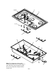
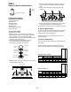
STEP 2
Replace All Burner and Valve Orifices
Orifice Size Stamped
Valve
Orifice
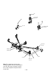
A. To Remove the Cooktop
Cooktop removal is required for:
• Gas piping inspection
• Wiring service
• Valve replacement
• Jet holder service
• Manifold service
• Indicator light replacement
• Bezel replacement
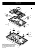
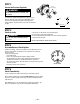
To remove the cooktop:
1. Remove the valve knobs.
2. Remove the burner caps and main burner head (brass).
3. Remove the brass nut using a 1-1/16" socket or adjustable
wrench and lift the burner ring from the assembly.
4. Remove the large brass orifice tube from the center of each
burner base using a 25/32" socket.
5. Lift each burner base and disconnect the push-on
wire terminal from the spark electrode. Place
the burner base assemblies in a safe place.
Locator Pin
Electrode
Main Orifice
Burner Ring
Locking Nut
Burner Base
Burner Head
(Brass)
Burner Ring
(Aluminum)
Burner Cap
Simmer Orifice
6. Remove the left screws holding the bezels for the left front
and right front gas valve knobs.
Remove Screws
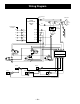
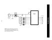
7. Raise the cooktop front about 6" and disconnect the 6 pin
connector under the cooktop and behind the right front
valve.
8. Push the spark electrode wire through the holes in the
cooktop.
9. Pick the cooktop straight up and place in a safe area where
it will not be scratched or accidently knocked over.
10. To install the countertop, reverse the procedure 1 through 9.
B. To Access Burner Orifices:
Unscrew the orifice using an appropriately sized conventional
socket or nut driver. Use a piece of sticky tape in socket to
prevent the loose orifice from falling out.
Verify that the orifices in the kit match the chart sizes and
replace the orifices.
C. To Access Valve Orifices:
Using a small 1/8" flat-blade screwdriver, carefully remove the
valve orifices.
Replace each orifice with the marked orifice from the kit.
Ensure that the replaced orifice is firmly seated in the valve.
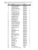
BURNER NATURAL GAS BTU RATES
MAIN SIM VALVE HI LO SIM
(REAR) 1.59 mm 0.57 mm 0.71 mm 12k 2490 1200 RED “P”
(FRONT) 1.45 mm 0.57 mm 0.71 mm 10.5k 2490 1200 ORANGE “P”
(CENTER) 1.78 mm 0.61 mm 0.71 mm 15k 3400 1200 YELLOW “V”
MAIN ORIFICE COLOR
*Simmer orifices are all brass because they are too small to color.
*ID code “letters” are stamped on orifice body.
ORIFICE/JET SIZES – LP
SIMMER ORIFICE CODE*
BURNER LP GAS BTU RATES
MAIN SIM VALVE HI LO SIM
(REAR) 0.81 mm 0.34 mm 0.46 mm 8.5k 2330 1100 WHITE “E”
(FRONT) 0.81 mm 0.34 mm 0.46 mm 8.5k 2330 1100 WHITE “E”
(CENTER) 1.1 mm 0.37 mm 0.46 mm 15k 2440 1100 BLACK “G”
MAIN ORIFICE COLOR
SIMMER ORIFICE CODE*
ORIFICE/JET SIZES – NATURAL