Monnit Wireless Sensors and Ethernet Gateway User’s Guide For Use With iMonnit Online Software and iMonnit Express PC Software MonnitLink™ Ethernet Gateway Quick Start • Create a Monnit user account with assigned wireless gateways and sensors. • Attach the antenna to the antenna connector on the back panel of the Ethernet gateway (make sure the connection is snug, but do not overtighten). • Plug an Ethernet cable with internet connectivity into the gateway.
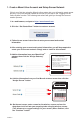
1. Create a Monnit User Account and Setup Sensor Network If this is your first time using the iMonnit online system site, you will need to create a new account. If you have already created an account you can skip to the “Logging into the Online System” section. The following instructions will guide you through the account creation process. 1. In a web browser, navigate to https://www.imonnit.com. 2. Click the “Get Started Here” button to create an account. 3.
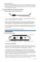
7. Confirmation Screen. When you have finished adding the sensor, you will see a confirmation screen. At this point you can assign notifications to the sensor (see Using The iMonnit™ Online Wireless Sensor System) , assign additional sensors to your account or click “Done” to go to your sensors overview page. 2. Using the MonnitLink™ Ethernet Gateway 1. Understanding the Ethernet Gateway Lights 1 2 3 Front of Ethernet Gateway Light 1 - Indicates the Ethernet cable is plugged in.
3. Configuring The Ethernet Gateway The Ethernet Gateway collects data from all sensors within range and is preconfigured to batch deliver the sensor messages to the online system every 5 minutes. The Ethernet Gateway uses DHCP (Dynamic Host Configuration Protocol) to automatically acquire a network address from the LAN (Local Area Network).
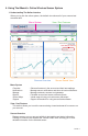
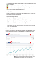
4. Using The iMonnit™ Online Wireless Sensor System 1. Understanding The Online Interface When you log into the online system, the default view shows all of your sensors last recorded data. Menu System View / Sort Features Date Range Selector Sensors Overview Sensor Details View Menu System Overview Notifications Manage Reports Sensor Maps Support - Shows all sensors in the account and their last readings. - Manage sensor notifications and show all sent notifications.
To the left side of each sensor row is an indicator to help you understand the current status of the sensor. Sensor is checking in and within user defined safe parameters. Sensor has met or exceeded a user defined threshold or triggered event. Sensor has not checked in (inactivity alert sent). No sensor readings will be recorded (Inactive) Sensor Details View Clicking on a sensor row on the “Overview” page expands the row to include a detailed sensor view for the selected sensor.
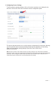
3. Configuring Sensor Settings To edit a sensors operation settings, click on the sensor overview row to display the details view. Click on the “Edit” tab to access the sensor configuration panel. The sensor edit panel allows you to set the primary configurations for the sensor. Mousing over the question mark icon by each setting will provide an explanation of that setting. When you have finished making changes, press the “Save” button at the bottom of this section.
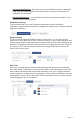
4. Sensor and/or Gateway Notification(s). Notifications for a single sensor can be created, deleted or edited by clicking the “Notifications” tab in a sensor’s detail view. Notifications can be created, deleted or edited for any sensor or group of sensors by clicking on “Notifications” in the main menu. Create a New Notification Toggle On/Off Click to Open Detail View Send Test Edit Delete When creating a notification, you will need to select the type of notification to create.
• Advanced Notifications - Allows the user to set notifications based on advanced rules, such as comparing past data points with the current one to determine if a notification should be sent. • Existing Notifications - Use notifications that have already been created on your account with the selected sensor.
Devices to Notify If you have a Monnit Control or Notifier A/V device on your network, you will also see a “Devices to Notify” tab. This will allow the notification to interact with these types of devices. Select a device from the list on the left and click the arrow button to add it to the recipient list. Clicking the control icon toggles their setting. Note: Control devices have two relays per device that are controlled separately. You can turn a relay on, off or toggle the state.
6. Calibrating Sensor Data Certain wireless sensors can be calibrated for more accurate readings (ex. temperature sensors). If calibration is possible for a sensor, the “Calibrate” tab will be visible in the detail view. To calibrate a sensor, replace the last reading with the more accurate reading and click “Calibrate”. All future readings from the sensor will be based off the new calibration setting. 7.
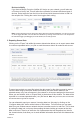
5. Advanced Settings and Interfacing with the Monnit Ethernet Gateway Through iMonnit. 1. Ethernet Gateway Edit Screen When you log into the online system, the default view shows all of your sensors last recorded data. The name can be edited to whatever you prefer. The gateway type should NOT be edited, unless you are directed to do so by a Monnit Support Representative. The unit’s MAC Address is viewable here, should you need to access it.
To set the Static IP, uncheck the Use DHCP box and fill in the settings: The force transmit on Aware box tells the gateway to deliver immediately the messages marked as Aware from the sensors. If this box is unchecked and the setting is saved, then the gateway only dumps the sensor messages it has been collecting on the Heartbeat Interval. This allows for controlled communication when sporadic communication from the gateway is either unacceptable or not ideal. 2.
MODBUS TCP Interface Use MODBUS TCP software to pull in gateway and sensor data. Monnit provides a register map. Check the box to make the interface Active and Save. The MODBUS TCP Interface will store all data values in 16-bit registers.
Data 1 Sensor Data Field 1 40109 108 Data 2 Sensor Data Field 2 40110 109 Data 3 Sensor Data Field 3 40111 110 Data 4 Sensor Data Field 4 40112 111 Data 5 Sensor Data Field 5 40113 112 Data 6 Sensor Data Field 6 40114 113 Data 7 Sensor Data Field 7 40115 114 Data 8 Sensor Data Field 8 40116 115 SNMP Poll and Trap Interface Use SNMP software to pull in gateway and sensor data. Monnit provides a .MIB file. There are four available interfaces.
Ethernet Gateway MIB tree with a short description of each field: EGW Data Description *GW Section Gateway Serial ID *Version Gateway Firmware Version *WD Count Wireless Device Count *WNetSection *WD Entry *Index PAGE 16 Gateway Section *GW Serial Wireless Network Seciont Wireless Device Entry Index Number *Serial Wireless Device Serial ID *Type Device Type (eg temp, water, motion sensor, etc) *Age Number of seconds since last data recording *Active Indicates if the wireless device is re
6. Setting up the Ethernet gateway for use with iMonnit Express iMonnit Express (PC Software) Setup Visit http://www.monnit.com/support/downloads/ to download and install the iMonnit Express software. • Launch the iMonnit Express installer and follow the on-screen instructions. • Launch the iMonnit Express program. • Activate the Express software with the code you received when purchasing. • Add the gateway(s) and wireless sensors to the software.
• Click on “About”, then “Local IP Addresses” and make note of the IP address that your computer is using on your network. • Connect the Ethernet Gateway directly to the Ethernet port of your PC using a standard Ethernet cable. Confirm that the PC has no other internet connection (turn off Wi-Fi). Confirm the PC firewall does not prohibit an inbound connection. Plug power cable into the Ethernet gateway. • Plug in the power cable.
• When finished, click the “Reboot” button on the top right side of the page to restart the gateway. • When the lights begin flashing on the gateway, you can unplug the power to the gateway and disconnect it from the computer. • Reactivate the Wi-Fi or other Internet connection for the computer, so it can connect to the network. • Plug your Ethernet gateway into your Internet router and power up the Ethernet gateway. All three lights should go green now, and your gateway should report into Monnit Express.
Error Reporting, Troubleshooting and Support For technical support and troubleshooting tips please visit our support library online at http://www.monnit.com/support/. If you are unable to solve your issue using our online support, email Monnit support at support@monnit.com with your contact information and a description of the problem, and a support representative will call you within one business day. For error reporting, please email a full description of the error to support@monnit.com.
(b) As a condition to Monnit’s obligations under the immediately preceding paragraphs, Customer shall return Products to be examined and replaced to Monnit’s facilities, in shipping cartons which clearly display a valid RMA number provided by Monnit. Customer acknowledges that replacement products may be repaired, refurbished or tested and found to be complying. Customer shall bear the risk of loss for such return shipment and shall bear all shipping costs.
Certifications United States FCC This equipment has been tested and found to comply with the limits for a Class B digital devices, pursuant to Part 15 of the FCC Rules. These limits are designed to provide reasonable protection against harmful interference in a residential installation. This equipment generates, uses, and can radiate radio frequency energy and, if not installed and used in accordance with the instruction manual, may cause harmful interference to radio communications.
Canada (IC) English Under Industry Canada regulations, this radio transmitter may only operate using an antenna of a type and maximum (or lesser) gain approved for the transmitter by Industry Canada. To reduce potential radio interference to other users, the antenna type and its gain should be so chosen that the equivalent isotropically radiated power (e.i.r.p.) is not more than that necessary for successful communication.
Additional Information and Support For additional information or more detailed instructions on how to use your Monnit Wireless Sensors or the iMonnit Online System, please visit us on the web at http://www.monnit.com/support/. Monnit Corporation 7304 South Cottonwood Suite #204 Midvale, Utah 84047 801-561-5555 www.monnit.com All trademarks are property of Monnit. © 2009-2014 Monnit Corp. All Rights Reserved.