
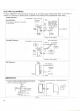
Specifications


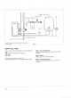


Step
8:
Install
the
Spill
Tray
Place
the
spill
tray
on the
floor where
you
plan
to
locate
your
neater.
Remove
the 2
sets
of
screws from
the
cabinet (Figure
12).
Position
the
heater
on the
spill tray
so the
legs
of the
cabinet
fit
into
the
circular indentations
in the
spill
tray
(Figure 12).
Screws
Retainers
Fig.
12
Legs
Spill
Tray
Step
9:
Level
the
cabinet
In
order
for
heater
to
operate properly.
It
must
be
positioned
on a
level surface. Ensure proper leveling
by
adjusting each
leg and by
using
a
carpenters level
to
check both side
to
side,
and
front
to
back level
condition.
Attach
and
tighten both sets
of
retainers
and
screws.
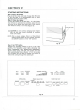
Step
10:
Install
the
Joint
Pipe
At
the
rear
of the
heater,
slide
the
large
end
opening
of
the
joint pipe into
the
exhaust port
outlet
of the
heater.
Be
sure
the
joint
pipe
is
fully
seated.
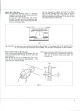
Slide
the
fabric cover over
the
joint pipe (Figure 13).
The
o-rings
that
seal
the
joint
pipe
may be dry and
tight.
A
little
soapy water will ease
installation.
Fabric Cover
Joint
Pipe
Fig.
13
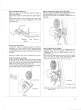
Step
11:
Connect
the
Heater
to the
Flue Pipe
Move
the
heater toward
the
wall, guiding
the
joint pipe
into
the
center port
of the
flue pipe (Figure 14).
Be
sure
the
joint pipe
is
completely inserted into
the
flue pipe.
Step
12:
Install
the Air
Damper
If
installation
is
standard (that
is no
extension kits
are
required),
place
the air
damper marked with
a
"STANDARD"
over
the air
intake flange
on the
flue
pipe (Figure 15).
Place
the
hose band around
the end of the air
supply
hose.
Push
the air
supply hose onto
the air
intake
flange
and
secure
the
hose with
the
hose band.
NOTE:Do
not
place
intake
hose
onto
metal
capped
exhaust
port.
13