
Technical data
104 FastIron Ethernet Switch Administration Guide
53-1002637-02
Hitless management on the FSX 800 and FSX 1600
3
Separate data and control planes
The FSX 800 and FSX 1600 management modules have separate data and control planes. The
data plane forwards traffic between the switch fabric modules and all of the Interface modules in
the chassis. The control plane carries traffic that is destined for the CPU of the active management
module. Control plane traffic includes the following:
• Management traffic
• Control protocol traffic
• In some cases, the first packet of a data flow
During a controlled or forced switchover, the data plane is not affected. Traffic in the forwarding
plane will continue to run without interruption while the standby management module takes over
operation of the system. However, traffic in the control plane will be minimally impacted.
Real-time synchronization between management modules
Hitless management requires that the active and standby management modules are fully
synchronized at any given point in time. This is accomplished by baseline and dynamic
synchronization of the modules.
When a standby management module is inserted and becomes operational in the FSX 800 or FSX
1600 chassis, the standby module sends a baseline synchronization request to the active
management module. The request prompts the active management module to copy the current
state of its CPU to the standby CPU, including:
• Start-up and run-time configuration (CLI)
• Layer 2 protocols – Layer 2 protocols such as STP, RSTP, MRP, and VSRP run concurrently on
both the active and standby management modules.
• Hardware Abstraction Layer (HAL) – This includes the prefix-based routing table, next hop
information for outgoing interfaces, and tunnel information.
• Layer 3 IP forwarding information – This includes the routing table, IP cache table, and ARP
table, as well as static and connected routes.
• If NSR is enabled, OSPFv2 and OSPFv3 information is copied to the standby.
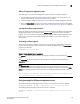
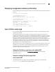
As baseline synchronization is performed, the console of the active management module displays
the progress of the synchronization.
ACTIVE: Detected Stdby heart-beat
ACTIVE: Standby is ready for baseline synchronization.
ACTIVE: Baseline SYNC is completed. Protocol Sync is in progress.
ACTIVE: State synchronization is complete.
The first message indicates that the active management module has detected the standby
management module. The second message indicates that the standby module has been
hot-inserted and is ready for baseline synchronization. The third message is seen when baseline
synchronization is completed, and the fourth message is seen when protocol synchronization is
completed.
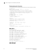
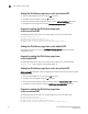
The console of the standby management module also displays the progress of the synchronization.
STBY: Baseline SYNC is completed. Protocol Sync is in progress.
STBY: State synchronization is complete.
The first message indicates that baseline synchronization is completed, and the second message
indicates that protocol sychronization is completed.